Description
System Architecture & Operational Principle
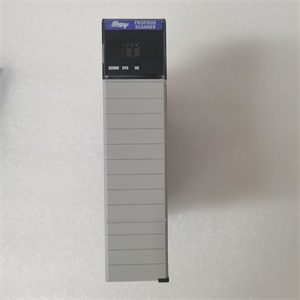
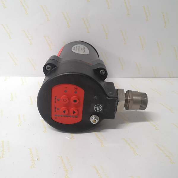
The 85UVF1-1QD is a field-mounted ultraviolet flame scanner equipped with an integral amplifier, designed for installation on combustion chambers or burner fronts where direct flame visibility is maintained. Positioned at Level 0 (Process) of the Purdue Model, it interacts directly with burner management systems (BMS) or safety-rated PLCs responsible for fuel valve actuation and combustion safeguarding.
Upstream, the BMS initiates a trial-for-ignition sequence and awaits a flame-established signal from the 85UVF1-1QD. The scanner continuously samples UV radiation in the 190–260 nanometer band, characteristic of hydrocarbon combustion. Upon detection, the integral amplifier processes the signal and outputs a 4–20 mA current loop proportional to flame intensity. This signal is interpreted by the BMS to either continue normal operation or execute a safety shutdown (fuel cut-off) upon flame loss.
The integral amplifier eliminates the need for an external signal conditioner, reducing wiring complexity and potential failure points. The 4–20 mA output is inherently noise-resistant, making it suitable for long cable runs in electrically noisy industrial environments. The NEMA 4 housing provides protection against dust, moisture, and corrosion, ensuring reliable operation in outdoor boiler houses, turbine enclosures, and process heater applications.

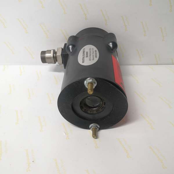
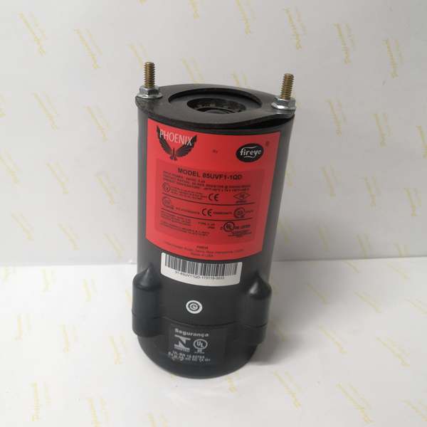
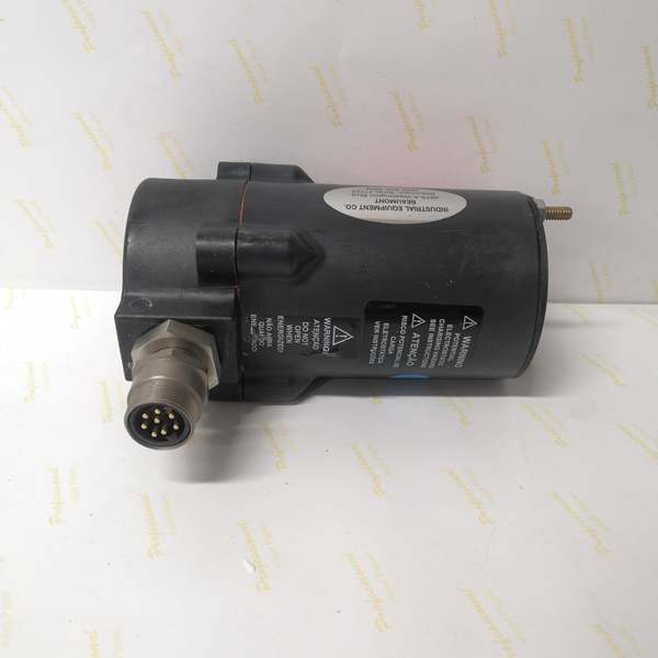
Fireye 85UVF1-1QD
Core Technical Specifications
-
Physical Interface: Two-wire shielded cable (18–22 AWG) for 4–20 mA loop; 24 VDC power over same pair
-
Signal Type: 4–20 mA current loop (proportional to flame intensity)
-
Detection Spectrum: 190–260 nm UV wavelength
-
Response Time: <1 second for flame detection; <3 seconds for flame failure recognition
-
Operating Temperature: -40°C to +75°C (-40°F to +167°F)
-
Environmental Rating: NEMA 4 (IP66 equivalent) weatherproof enclosure
-
Supply Voltage: 24 VDC nominal (18–32 VDC range)
-
Current Draw: 20 mA (no flame) to 100 mA (full flame) typical
-
Field of View: ~100° cone angle (line-of-sight dependent)
-
Electrical Connection: Screw terminals inside housing; pigtail leads to terminal block
-
Certifications: FM approved, CSA certified, CE marked
-
Weight: ~1.1 kg (2.4 lbs)
Customer Value & Operational Benefits
Simplified Wiring and Reduced Failure Points
The integral amplifier design removes the requirement for a separate signal conditioning unit, cutting installation time and eliminating a potential failure point. This is particularly valuable in retrofits where space is limited and additional components would complicate panel layouts.
Noise-Resistant Signal for Long Cable Runs
The 4–20 mA output signal is inherently immune to electrical noise and voltage drops over distance, allowing reliable communication with BMS panels located hundreds of feet away. This ensures accurate flame status reporting even in electrically noisy environments like turbine halls or refinery process units.
Rugged Construction for Harsh Environments
The NEMA 4 housing withstands exposure to rain, snow, dust, and corrosive atmospheres common in industrial combustion applications. Combined with a wide operating temperature range, this extends maintenance intervals and reduces lifecycle costs compared to less durable flame detectors.
Fireye 85UVF1-1QD
Field Engineer’s Notes (From the Trenches)
When installing the 85UVF1-1QD, keep the lens clean and free of soot or condensation—even a thin film can attenuate UV transmission and cause false flame loss signals. I’ve had to troubleshoot several nuisance trips where the scanner was working perfectly, but the lens was obscured by carbon buildup. Use a soft, lint-free cloth and isopropyl alcohol for cleaning; avoid abrasive materials that can scratch the quartz window. Also, ensure the 4–20 mA loop is wired in series with the BMS input and that the power supply is clean and well-regulated—ripple on the 24 VDC line can introduce noise that the BMS misinterprets as flame instability.
Real-World Applications
In a natural gas-fired power plant, the 85UVF1-1QD is mounted on the combustion liner of a 150 MW gas turbine. The scanner’s 4–20 mA output feeds the turbine control system, which requires a minimum 8 mA signal to confirm flame stability before increasing fuel flow. The integral amplifier’s fast response time (<1 second) allows the BMS to detect flameout within the required 2-second safety window, preventing unburnt fuel accumulation.
On a refinery process heater, the 85UVF1-1QD monitors the flame in a multi-burner furnace. The scanner is positioned to view the primary combustion zone of each burner, with the 4–20 mA signal indicating individual burner flame status. The BMS uses this data to implement staggered ignition sequences and to shut down specific burners if flame is lost, maintaining process continuity while ensuring safety.