Description
System Architecture & Operational Principle
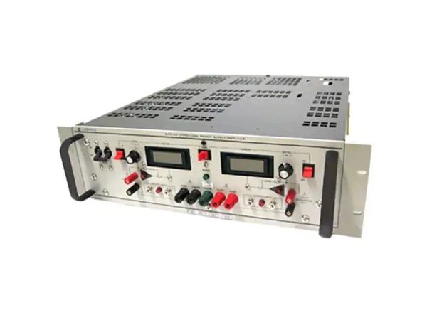
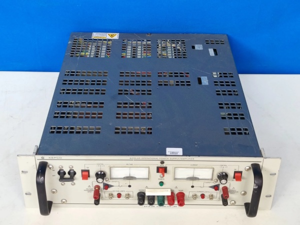
The KEPCO BOP20-20M is a high-precision bipolar DC power supply designed for applications requiring accurate voltage/current control and bidirectional power delivery. It operates as a standalone module or integrates into larger test systems, interfacing with:
-
Upstream: AC power sources (via rectifier/converter) or other power supplies for charging/discharging cycles.
-
Downstream: Loads such as motors, magnetic components (coils, transformers), or test equipment (e.g., oscilloscopes, data acquisition systems).
Core Functional Blocks
-
Power Conversion Stage: Converts AC input to DC output using high-efficiency rectifiers and filters. The bipolar design allows the output to swing between positive and negative voltages, enabling 4-quadrant operation (source/sink current in both polarities).
-
Control Circuitry: Uses a high-speed operational amplifier (op-amp) with feedback loops to regulate voltage and current. The control circuit ensures ≤35 μs rise/fall time and 10 kHz bandwidth, critical for dynamic testing applications.
-
Protection Mechanisms: Includes overvoltage (OVP), overcurrent (OCP), short-circuit (SCP), and thermal protection to safeguard the module and connected loads.
-
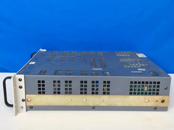
User Interface: Features a 50-terminal user port (rear) for remote control and monitoring, plus optional digital displays (via suffix “D”) for real-time feedback.
Operational Workflow
-
Input Power: The module accepts AC input (converted to DC internally) and regulates it to the desired output voltage/current.
-
Bidirectional Operation: In source mode, the module supplies power to the load (e.g., charging a capacitor). In sink mode, it absorbs power from the load (e.g., discharging a motor).
-
Feedback Control: The control circuit continuously monitors the output voltage/current and adjusts the power conversion stage to maintain stability (within ±0.1% accuracy).
-
Protection Activation: If a fault (e.g., overvoltage, overcurrent) is detected, the protection circuit shuts down the output and alerts the user via the user port or display.
Core Technical Specifications
|
Parameter
|
Specification
|
|---|---|
|
Output Voltage
|
±20 V DC (adjustable)
|
|
Output Current
|
±20 A DC (adjustable)
|
|
Power Rating
|
400 W (continuous)
|
|
Operation Mode
|
4-quadrant bipolar (source/sink current in both polarities)
|
|
Rise/Fall Time
|
≤35 μs (10%–90% of full scale)
|
|
Bandwidth
|
10 kHz (voltage/current)
|
|
Accuracy
|
±0.1% (voltage/current)
|
|
Protection
|
Overvoltage, overcurrent, short-circuit, thermal shutdown
|
|
User Interface
|
50-terminal user port (rear); optional digital display (suffix “D”)
|
|
Operating Temperature
|
0°C to +40°C (ambient)
|
|
Weight
|
~29 kg (64 lbs)
|
KEPCO BOP20-20M
Customer Value & Operational Benefits
1. High Precision for Critical Applications
The BOP20-20M’s ±0.1% voltage/current accuracy and 10 kHz bandwidth make it ideal for precision testing (e.g., characterizing magnetic components, calibrating sensors). For example, in motor testing, the module can accurately simulate load conditions (e.g., starting current, regenerative braking) to validate motor performance.
2. Bidirectional Power Delivery
The 4-quadrant operation allows the module to both supply and absorb power, eliminating the need for additional equipment (e.g., separate power supplies and loads). This is critical for applications like motor testing (simulating regenerative braking) or battery cycling (charging/discharging batteries).
3. Fast Dynamic Response
The ≤35 μs rise/fall time enables the module to handle rapid changes in load conditions (e.g., switching from charging to discharging a capacitor). This is essential for dynamic testing (e.g., measuring the response of a power supply to sudden load changes).
4. Robust Protection for Reliability
The built-in overvoltage, overcurrent, and short-circuit protection safeguards the module and connected loads from damage. For example, if a motor draws too much current during startup, the OCP will shut down the output, preventing damage to the motor or module.
Field Engineer’s Notes (From the Trenches)
When installing the BOP20-20M, always verify the AC input voltage (110–240 V AC, 50/60 Hz) with a multimeter—using an incorrect voltage can damage the rectifier stage. I once saw a technician connect the module to a 480 V AC supply, which immediately fried the input filter.Check the load connections—ensure the load is connected to the correct output terminals (±V, ±I) to avoid reverse polarity. Reverse polarity can damage the load or the module’s protection circuitry.Test the protection features after installation—intentionally trigger an overcurrent fault (e.g., short-circuit the output) to verify that the protection circuit shuts down the output and alerts the user. This ensures the module will protect itself and the load in real-world scenarios.KEPCO BOP20-20M
Real-World Applications
1. Motor Testing
A motor manufacturer uses the BOP20-20M to test brushless DC motors (BLDCs) for electric vehicles. The module simulates the motor’s operating conditions (e.g., starting current, regenerative braking) by delivering precise voltage/current profiles. The 4-quadrant operation allows the module to absorb power from the motor during braking, mimicking real-world driving conditions.
2. Magnetic Component Characterization
A research lab uses the BOP20-20M to characterize inductors and transformers for renewable energy systems. The module delivers a sinusoidal voltage (10 kHz) to the component and measures the resulting current, allowing engineers to calculate inductance, resistance, and core losses. The high bandwidth (10 kHz) ensures accurate measurement of dynamic properties.
3. Battery Cycling Tests
A battery manufacturer uses the BOP20-20M to perform charge/discharge cycles on lithium-ion batteries. The module charges the battery at a constant current (10 A) until it reaches 4.2 V, then discharges it at a constant current (10 A) until it reaches 3.0 V. The bidirectional operation eliminates the need for separate chargers and loads, simplifying the test setup.