Description
System Architecture & Operational Principle
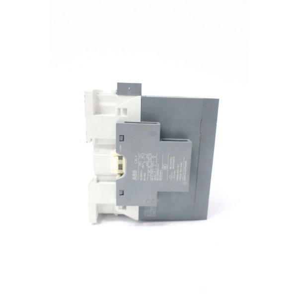
The ABB AF65-30-11-13 is a 3-pole contactor designed for use in Level 1 (Device) or Level 2 (Control) of the Purdue Model, depending on the application. It operates in conjunction with:
-
Upstream Control Devices: Receives command signals from programmable logic controllers (PLCs), motor starters, or pushbutton stations via its 100-250V AC/DC control coil.
-
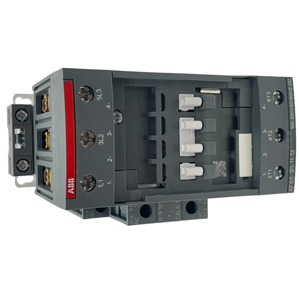
Downstream Loads: Connects 3-phase power (up to 690V AC) to 3-phase motors, resistive heaters, or other high-power devices through its main contacts.
-
Auxiliary Circuits: Provides 1 normally open (NO) and 1 normally closed (NC) contact for status feedback (e.g., “contactor closed” signals to a PLC or indicator light) or interlock logic (e.g., preventing simultaneous operation of two contactors).
The contactor’s electronic coil interface is a key architectural advantage: it accepts a wide range of control voltages (100-250V AC/DC) without requiring coil changes, reducing inventory and simplifying global deployments. The coil also uses 80% less energy than traditional wound coils, lowering operational costs. Built-in surge suppression protects against voltage spikes, eliminating the need for external suppressors.

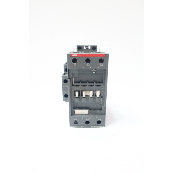
ABB AF65-30-11-13
Core Technical Specifications
-
Rated Operational Voltage (Main Circuit): 690V AC / 220V DC
-
Rated Operational Current (AC-3): 65A (@ 400V); 39A (@ 690V)
-
Rated Operational Current (AC-1): 105A (@ 690V)
-
Control Coil Voltage: 100-250V AC/DC (50/60 Hz)
-
Number of Poles: 3 (main contacts)
-
Auxiliary Contacts: 1 NO + 1 NC (side-mounted)
-
Conventional Free-Air Thermal Current (Ith): 105A (@ 40°C)
-
Mechanical Lifespan: 10 million cycles
-
Electrical Lifespan: 1.2 million cycles (AC-3)
-
Terminal Type: Screw terminals (main circuit); flexible/rigid conductors (0.75-2.5 mm² control circuit)
-
Operating Temperature: -40°C to +70°C (without thermal overload relay); -25°C to +60°C (with thermal overload relay)
-
Weight: 0.97 kg (2.403 lbs)
Customer Value & Operational Benefits
Reduced Inventory Complexity
The AF65-30-11-13’s wide control voltage range (100-250V AC/DC) eliminates the need for multiple contactor models to support different control voltages. This simplifies spare parts management and reduces warehouse costs—critical for facilities with global operations.
Energy Efficiency & Cost Savings
The electronic coil uses 80% less energy than traditional coils, resulting in significant long-term cost savings. For example, a facility with 100 contactors could save hundreds of dollars annually in electricity costs.
Enhanced Reliability
Built-in surge suppression protects against voltage spikes caused by lightning, switching, or grid fluctuations. This reduces the risk of contactor failure and extends equipment lifespan—key for mission-critical applications like motor control.
Flexible Integration
Auxiliary contacts (1NO+1NC) enable seamless integration with PLCs or control systems for status monitoring and interlock logic. For instance, the NO contact can trigger a “motor running” indicator, while the NC contact can disable a start button to prevent accidental restarts.
Field Engineer’s Notes (From the Trenches)
When installing the AF65-30-11-13, always verify the control coil voltage—even if the label says 100-250V AC/DC. I once worked on a project where a contractor accidentally connected a 24V DC coil to a 120V AC supply, frying the coil instantly. Use a multimeter to confirm the control voltage before powering up.Another gotcha: tighten screw terminals to the specified torque (0.8-1.2 Nm for main contacts). Over-tightening can strip the threads, while under-tightening causes arcing and premature failure. I’ve seen contactors fail because of loose connections—always use a torque wrench.If the contactor chatters (rapidly opens/closes), check for voltage drops in the control circuit. Long wire runs or undersized conductors can cause the coil to lose power, leading to chattering. Use a larger gauge wire or add a local power supply near the contactor.
Real-World Applications
-
HVAC System Motor Control:The AF65-30-11-13 switches 3-phase power to a 30 kW HVAC fan motor (400V AC-3). The auxiliary NO contact sends a “fan running” signal to the building management system (BMS), while the NC contact disables the start button until the motor stops—preventing accidental restarts.
-
Water Treatment Pump Station:Used to control a 45 kW water pump motor (690V AC-3). The contactor’s built-in surge suppression protects against voltage spikes from the grid, while the auxiliary contacts interlock with a valve contactor to ensure the pump doesn’t start until the inlet valve is open.
ABB AF65-30-11-13
High-Frequency Troubleshooting FAQ
Q: What does the “13” suffix mean in ABB AF65-30-11-13?
A: The suffix denotes the control coil voltage range. “13” corresponds to 100-250V AC/DC. Other suffixes include “11” (24-60V AC/DC) and “12” (48-130V AC/DC). Always match the suffix to your control circuit voltage to avoid damage.
Q: Can I replace an older ABB AF65-30-00-13 contactor with AF65-30-11-13?
A: Yes, but you must add auxiliary contacts (1NO+1NC) to the AF65-30-00-13. The AF65-30-11-13 includes these contacts as standard, so replacing it requires no additional wiring for auxiliary functions. Verify the mounting dimensions (they are identical) and control coil voltage.
Q: Why is my AF65-30-11-13 contactor not closing?
A: Check three things first:
-
Control voltage: Ensure the coil is receiving 100-250V AC/DC (use a multimeter).
-
Auxiliary contact alignment: Make sure the auxiliary contacts are not blocking the main contacts (rare, but possible if misaligned during installation).
-
Overload relay: If the contactor is paired with a thermal overload relay, check if it has tripped (reset it if necessary).
Q: How do I wire the auxiliary contacts on AF65-30-11-13?
A: The auxiliary contacts are labeled 13-14 (NO) and 21-22 (NC). Connect the NO contact (13-14) to a PLC input for “contactor closed” status. Connect the NC contact (21-22) to a stop button or interlock circuit—when the contactor closes, the NC contact opens, disabling the start button.
Commercial Availability & Pricing
Please note: The listed price is not the actual final price. It is for reference only and is subject to appropriate negotiation based on current market conditions, quantity, and availability.