Description
System Architecture & Operational Principle
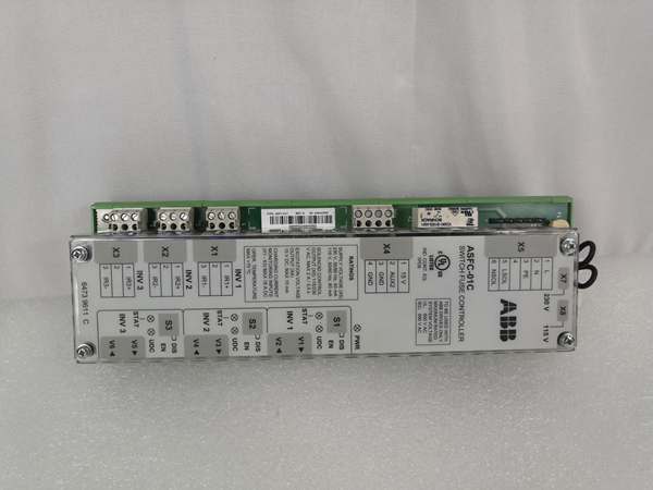
The ABB RDCU-12C is a core control board in the Level 1 (Device) or Level 2 (Control) of the Purdue Model, depending on the application. It resides within the ACS800 VFD’s control cabinet and acts as the central hub for all control and communication functions.
Upstream Communication
Receives command signals (e.g., speed setpoints, start/stop commands) from higher-level systems like SCADA, PLCs, or HMIs via:
-
Ethernet: 10/100 Mbps port supporting Modbus TCP/IP (for integration with plant-wide networks).
-
Serial: RS-232/485 ports for legacy devices (e.g., Modbus RTU).
These signals are processed by the RDCU-12C’s internal microprocessor to execute user-defined control logic (e.g., adjusting motor speed based on sensor feedback).
Downstream Communication
Transmits real-time data (e.g., motor speed, current, fault codes) from the VFD to external systems using the same protocols. It also interfaces with field devices (e.g., sensors, actuators) via:
-
Analog Inputs: 3 channels (2x 0-20mA, 1x ±10V) for collecting sensor data (e.g., temperature, pressure).
-
Digital Inputs: 7 channels (24V DC) for receiving discrete signals (e.g., limit switches, pushbuttons).
-
Relay Outputs: 3 channels (2A @ 24V DC) for controlling actuators (e.g., solenoid valves, contactors).
Operational Advantages
-
High Precision: 12-bit analog input resolution enables accurate measurement of process variables (e.g., motor current), critical for applications like precision manufacturing.
-
Noise Immunity: Galvanically isolated digital inputs prevent electrical noise from affecting signal integrity—essential in industrial environments with high EMI.
-
Modular Design: Plug-and-play installation reduces setup time; compatible with ACS800’s RMIO (Motor Control and I/O) board for seamless integration.

ABB RDCU-12C
Core Technical Specifications
|
Attribute
|
Specification
|
|---|---|
|
Power Supply
|
24V DC ±10% (input via X34 terminal)
|
|
Analog Inputs
|
3 channels (2x differential current: 0-20mA, 1x differential voltage: ±10V); 12-bit resolution
|
|
Analog Outputs
|
2 channels (0-20mA); 10-bit resolution
|
|
Digital Inputs
|
7 channels (24V DC); galvanically isolated; logical thresholds: <8V DC (“0”), >12V DC (“1”)
|
|
Relay Outputs
|
3 channels (changeover contact); 2A @ 24V DC or 115/230V AC
|
|
Communication
|
1x Ethernet (10/100 Mbps, Modbus TCP/IP); 1x RS-232/485 (Modbus RTU)
|
|
Operating Temperature
|
0°C to +60°C (32°F to 140°F)
|
|
Storage Temperature
|
-40°C to +70°C (-40°F to 158°F)
|
|
Dimensions
|
120 mm (W) x 80 mm (H) x 40 mm (D)
|
|
Weight
|
0.5 kg (1.1 lbs)
|
|
Certifications
|
CE, UL, RoHS
|
Customer Value & Operational Benefits
Reduced Downtime with Precise Diagnostics
The RDCU-12C’s built-in diagnostic capabilities (e.g., real-time fault logging, status LEDs) enable quick identification of issues (e.g., “analog input out of range” or “communication timeout”). This reduces mean time to repair (MTTR) by up to 30% compared to systems without advanced diagnostics.
Improved Process Efficiency
With support for vector control and PID algorithms, the RDCU-12C optimizes motor speed and torque, reducing energy consumption by up to 20% in applications like pump and fan control. For example, a water treatment plant using the RDCU-12C reported a 15% reduction in energy costs after upgrading from a basic VFD.
Seamless Integration with ABB Ecosystem
The RDCU-12C is fully compatible with ABB’s 800xA automation platform and ACS800 VFDs, eliminating the need for custom integration. This simplifies deployment and reduces engineering costs— a chemical plant saved $10,000 in integration fees by using native 800xA support.
Scalable for Future Expansions
The module’s support for multiple communication protocols (Modbus TCP/IP, RS-232/485) allows facilities to scale their automation systems without replacing the entire VFD. For example, a manufacturing plant added a new SCADA system using Modbus TCP/IP, and the RDCU-12C integrated seamlessly without hardware changes.
Field Engineer’s Notes (From the Trenches)
When installing the RDCU-12C, always verify the 24V DC power supply—a low input voltage (below 21.6V DC) can cause the module to malfunction. I once saw a site where a loose power terminal caused intermittent faults—using a multimeter to measure the voltage at the X34 terminal fixed the issue in 5 minutes.Another gotcha: use shielded cables for analog inputs—unshielded cables can pick up EMI from nearby motors, leading to inaccurate readings. I recommend using twisted-pair shielded cables with ferrite cores for analog signals.If the RDCU-12C’s “FAULT” LED is red, check the fault log—the module stores up to 100 fault events with timestamps. Use ABB’s DriveWindow software to download the log and identify the root cause (e.g., “overcurrent” or “communication error”).ABB RDCU-12C
Real-World Applications
Power Generation: Wind Turbine Pitch Control
The RDCU-12C is used to control the pitch of wind turbine blades, adjusting the angle to optimize energy capture. It receives wind speed data from an anemometer (analog input) and sends commands to the pitch actuator (relay output). The Modbus TCP/IP communication enables remote monitoring from the wind farm’s SCADA system.
Chemical Processing: Pump Station Control
In a chemical plant, the RDCU-12C controls a pump station using 0-20mA analog inputs (for flow rate sensors) and relay outputs (for pump starters). It executes a PID loop to maintain constant flow rate, adjusting the pump speed via the ACS800 VFD. The galvanically isolated digital inputs prevent noise from affecting the flow meter signals.
Manufacturing: Conveyor Belt Synchronization
A manufacturing plant uses the RDCU-12C to synchronize conveyor belts, ensuring smooth material flow. It receives speed setpoints from a PLC (via Modbus TCP/IP) and sends real-time speed data back to the PLC. The 12-bit analog input resolution enables precise speed control (within 0.1% of setpoint), reducing product jams.
High-Frequency Troubleshooting FAQ
Q: What does the “FAULT” LED on the RDCU-12C indicate?
A: The red “FAULT” LED indicates a critical error (e.g., overcurrent, communication timeout, or hardware failure). Check the fault log using ABB’s DriveWindow software—each fault has a unique code (e.g., “F001” for overcurrent) with a descriptive message.
Q: Why is the RDCU-12C not communicating with the SCADA system?
A: Check three things first:
-
Ethernet Cable: Ensure the cable is securely connected to the RDCU-12C’s Ethernet port and the SCADA system (use a CAT5e shielded cable).
-
IP Address: Verify the RDCU-12C’s IP address matches the SCADA system’s configuration (check the ACS800’s parameter settings).
-
Protocol: Ensure the SCADA system and RDCU-12C are using the same protocol (e.g., Modbus TCP/IP).
Q: How do I replace the RDCU-12C?
A: Follow these steps:
-
Power Down: Turn off the ACS800 VFD and disconnect it from the power supply.
-
Remove Cover: Unscrew the VFD’s front cover to access the RDCU-12C.
-
Disconnect Wires: Label and disconnect the power, analog, and digital wires from the RDCU-12C.
-
Remove Module: Unscrew the RDCU-12C from the RMIO board (use a Phillips screwdriver).
-
Install New Module: Secure the new RDCU-12C to the RMIO board and reconnect the wires (ensure correct polarity).
-
Power Up: Turn on the VFD and verify the RDCU-12C’s operation (check the “POWER” LED).
Q: Why are the analog inputs reading incorrectly?
A: Check three things:
-
Sensor Wiring: Ensure the sensor is connected to the correct analog input (e.g., 0-20mA sensor to AI1).
-
Shielding: Use shielded cables for analog inputs to reduce EMI.
-
Calibration: Verify the analog input calibration using ABB’s DriveWindow software—adjust the offset and gain if necessary.
Commercial Availability & Pricing
Please note: The listed price is not the actual final price. It is for reference only and is subject to appropriate negotiation based on current market conditions, quantity, and availability.