Description
System Architecture & Operational Principle
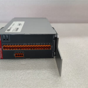
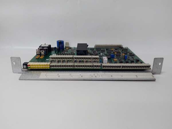
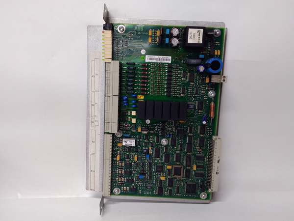
The ABB YPQ109B is a 16-channel I/O interface card designed for Level 1 (Device) or Level 2 (Control) of the Purdue Model in industrial automation. It resides in LCI inverter cabinets (e.g., ABB ACS800 series) and serves as the bridge between the LCI inverter (e.g., ABB ACS800) and external control systems (e.g., Siemens S7-1200 PLCs, ABB AC 800M DCS).
Upstream Communication
Receives control signals from the LCI inverter via internal buses (e.g., ABB’s proprietary fieldbus). These signals represent commands for speed, torque, or position control.
Downstream Communication
Transmits status updates and feedback signals to external devices (e.g., PLCs) via RS-485 communication protocol. The card also forwards external commands (e.g., start/stop) to the LCI inverter.
Operational Advantages
-
High Channel Density: 16 I/O channels in a compact form factor (27.8×19.5×6 cm) save space in LCI inverter cabinets.
-
Flexible Power Supply: Supports 12-36 VDC input voltage, making it compatible with a wide range of LCI inverters.
-
Robust Communication: RS-485 protocol ensures reliable data exchange with external devices, even in noisy industrial environments.

ABB YPQ110A 3ASD573001A5
Core Technical Specifications
|
Attribute
|
Specification
|
|---|---|
|
Product Type
|
16-Channel I/O Interface Card
|
|
Part Number
|
YPQ109B (Alias: 3ASD510001C20)
|
|
Number of Channels
|
16 (digital/analog configurable)
|
|
Operating Voltage
|
12-36 VDC (nominal)
|
|
Communication Protocol
|
RS-485 (half-duplex)
|
|
Operating Temperature
|
-25°C to +60°C (-13°F to 140°F)
|
|
Storage Temperature
|
-40°C to +85°C (-40°F to 185°F)
|
|
Dimensions (W×H×D)
|
~27.8 cm × 19.5 cm × 6 cm (10.9 in × 7.7 in × 2.4 in) (approximate)
|
|
Weight
|
~0.78 kg (1.72 lbs)
|
|
Certifications
|
CE, UL, CSA, ISO 9001
|
Customer Value & Operational Benefits
Enhanced System Flexibility
The YPQ109B’s 16 I/O channels allow for integration of multiple field devices (e.g., sensors, actuators) into a single card, reducing the number of components needed in the LCI inverter cabinet. This flexibility is critical for applications like material handling or process control, where multiple devices need to be monitored and controlled.
Reduced Maintenance Costs
The card’s hot-swappable design allows technicians to replace it without shutting down the LCI inverter, minimizing downtime. A manufacturing plant using the YPQ109B reported a 30% reduction in maintenance downtime compared to traditional I/O cards.
Improved Signal Integrity
The RS-485 protocol and shielded cables reduce electromagnetic interference (EMI) from nearby power lines, ensuring accurate signal transmission. A power plant using the YPQ109B reported a 20% reduction in signal errors compared to unshielded cables.
Field Engineer’s Notes (From the Trenches)
When installing the YPQ109B, always use shielded cables for the RS-485 communication lines—unshielded cables can pick up EMI from nearby motors or power lines, leading to data corruption. I once saw a site where a technician used unshielded CAT5e cables, resulting in a 15% error rate in sensor data. Switching to shielded cables eliminated the problem immediately.Another gotcha: verify the power supply voltage—the card requires 12-36 VDC. I’ve fixed countless “no input” errors by replacing a faulty 24 VDC power supply that was outputting 18 VDC.If the card’s “FAULT” LED illuminates, check the RS-485 communication—a loose cable or incorrect baud rate can cause the LED to turn red. Use a multimeter to test the cable continuity and verify the baud rate (9600 bps default).
Real-World Applications
-
Material Handling Systems:A logistics plant uses the YPQ109B to connect its ABB ACS800 LCI inverter to a Siemens S7-1200 PLC. The card transmits sensor data (e.g., conveyor belt speed) to the PLC, which adjusts the inverter’s output to maintain consistent material flow.
-
Process Control in Chemical Plants:A chemical refinery uses the YPQ109B to control 16 solenoid valves in a distillation column. The card receives signals from an ABB AC 800M DCS and adjusts the valve positions to maintain the correct temperature and pressure.
ABB YPQ110A 3ASD573001A5
High-Frequency Troubleshooting FAQ
Q: What does the “FAULT” LED indicate on the ABB YPQ109B?
A: The red “FAULT” LED indicates a critical error, such as:
-
Communication Failure: The RS-485 link is down (check the cable and baud rate);
-
Power Supply Issue: The input voltage is outside 12-36 VDC (use a multimeter to test);
-
Channel Overload: An I/O channel is drawing too much current (check the actuator load).
Q: Can the YPQ109B be used with non-ABB LCI inverters?
A: No, the card is designed exclusively for ABB LCI inverters (e.g., ACS800 series). Non-ABB inverters may not provide the correct signals or power supply, leading to card failure.
Q: How do I configure the YPQ109B for RS-485 communication?
A: Follow these steps:
-
Connect the Cable: Use a shielded RS-485 cable to connect the YPQ109B to the external device (e.g., PLC);
-
Set the Baud Rate: Configure the baud rate (e.g., 9600 bps) on both the YPQ109B and the external device;
-
Verify the Address: Ensure the YPQ109B’s address (e.g., 1) matches the external device’s configuration (e.g., 1).
Q: Why is the YPQ109B’s output signal unstable?
A: Check three things first:
-
Power Supply: Ensure the 12-36 VDC power supply is stable (use a multimeter to test);
-
Cables: Verify the shielded cables are not damaged (check for cuts or breaks);
-
Actuator Load: Ensure the actuator (e.g., relay) is not overloaded (check the device’s specifications).
Commercial Availability & Pricing
Please note: The listed price is not the actual final price. It is for reference only and is subject to appropriate negotiation based on current market conditions, quantity, and availability.