Description
System Architecture & Operational Principle
Core Technical Specifications
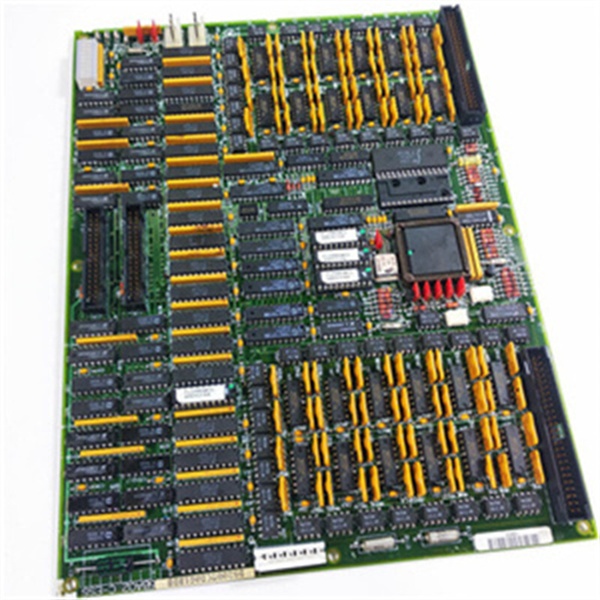
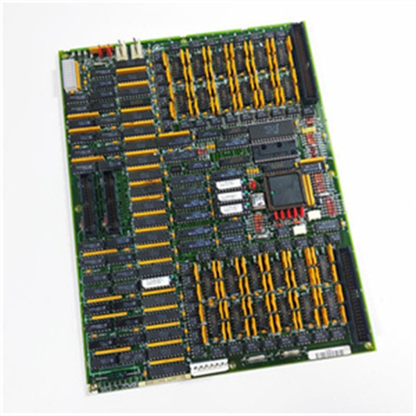
- Physical Interface: Dual 50‑pin IDC connectors (JX1, JX2) for IONET; JP power connector; JO1/JO2 output connectors
- Signal Type: Dry contact inputs (24 VDC nominal); relay‑drive outputs (non‑isolated)
- Channel Density: Configurable via terminal boards (typically 16 inputs / 16 outputs per board)
- Communication Bus: Mark V proprietary IONET high‑speed backplane
- Processing: Onboard microcontroller with PROM firmware storage
- Isolation: Input‑to‑backplane optical isolation (2500 Vrms test)
- Configuration: 8 jumpers (J1–J8) for IONET address, RS‑232, stall timer, test mode
- Diagnostics: 10‑LED array for channel status; 1 system run/fault LED
- Environmental: Operating temp −30°C to +65°C; 5–95% RH (non‑condensing)
- Power: Backplane‑powered (5 VDC, 200 mA typical)
- Weight: 0.7 kg
- Manual Reference: GEH‑6153 / Mark V TCDA Board Documentation
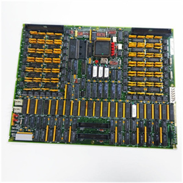
GE DS200TCDAG1BDB
Customer Value & Operational Benefits
The DS200TCDAG1BDB’s optical input isolation eliminates ground loops and noise-induced false triggers on critical safety interlocks (e.g., overspeed, vibration, flame detection). This directly reduces nuisance turbine trips, boosting unit availability and preventing costly unplanned outages in power generation and industrial turbine applications.
The 10‑LED diagnostic array provides real‑time, channel‑level status visibility, enabling technicians to pinpoint faulty inputs/outputs in seconds. IONET bus communication ensures rapid fault reporting to the main controller, while jumper‑configurable test modes (J8) simplify offline diagnostics. These features cut mean time to repair (MTTR) for digital I/O issues by up to 50%.
As a fully backward‑compatible revision of the TCDA family, the DS200TCDAG1BDB drops directly into existing Q11/Q51 slots without hardware or software modifications. Its robust design and readily available replacement stock extend the operational life of aging Mark V systems, deferring expensive forklift upgrades and preserving capital investment.
Field Engineer’s Notes (From the Trenches)
When commissioning or replacing a DS200TCDAG1BDB, never alter the IONET address jumpers (J4–J6) from factory defaults unless explicitly directed by the Mark V configuration software. Incorrect addressing will cause the board to drop off the IONET bus, resulting in a complete loss of digital I/O. Always verify the JP power connector is fully seated before powering up—loose power connections cause intermittent IONET faults that are notoriously difficult to trace. For input wiring, use twisted‑pair, shielded cable and ground the shield at the control cabinet end only to minimize EMI. When testing outputs, use the J8 test jumper to force outputs locally without energizing field devices, preventing accidental actuation of solenoids or relays during maintenance. Finally, always back up the board’s PROM configuration before replacement; manual reconfiguration of IONET parameters is time‑consuming and error‑prone.
Real-World Applications
- Gas Turbine Safety Interlock Monitoring
The DS200TCDAG1BDB acquires dry contact inputs from safety devices: overspeed switches, vibration probes, flame detectors, and emergency stop (E‑Stop) pushbuttons. Isolated inputs ensure reliable signal detection even in high‑EMI turbine environments. The board transmits these critical states over IONET to the Mark V controller, which executes safety logic to initiate turbine shutdowns when unsafe conditions are detected.
- Steam Turbine Auxiliary System Control
In combined‑cycle power plants, this module receives status inputs from auxiliary systems (lube oil pressure switches, seal air flow contacts, feed pump run permissives). It outputs control signals to TCRA relay boards, which actuate motor starters for lube oil pumps, seal air fans, and steam drain valves. Fast IONET communication ensures tight coordination between auxiliary systems and main turbine control logic.
GE DS200TCDAG1BDB
High-Frequency Troubleshooting FAQ
A: First, check the system LED for a fault indication. Verify the JP power connector is secure and 5 VDC backplane power is present. Inspect JX1/JX2 IONET cables for damage or loose connections. Confirm jumpers J4–J6 (IONET address) are set to the factory configuration for the Q11/Q51 core. A faulty onboard microprocessor or PROM will also cause IONET communication failure; in this case, the board requires repair or replacement.
A: Common causes include inadequate input wiring shielding, ground loops, or faulty field devices. Use a multimeter to verify 24 VDC is present at the input terminals. Check for loose connections at the DTBA/DTBB terminal boards. Ensure input signals are dry contacts (no external voltage) and that the optical isolation is intact. EMI from nearby high‑voltage cables can also corrupt inputs—reroute analog/digital wiring away from power cables.
A: Yes, the DS200TCDAG1BDB is fully backward‑compatible with all earlier TCDA revisions (1B, BCB, etc.). It uses the same backplane interface, pinout, and firmware structure. When replacing, match the jumper settings (J1–J8) from the old board to the new one; no software changes are required for basic operation.
A: Install jumper J8 to enable test mode. In this mode, the board disconnects from the IONET bus and allows local control of output channels via the front‑panel LEDs. Use this to verify output relay drivers and wiring without affecting turbine operation. Always remove J8 before returning the board to service to restore normal IONET communication.