Description
System Architecture & Operational Principle
Core Technical Specifications
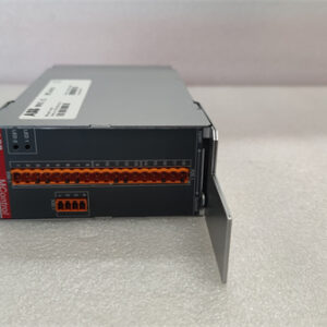
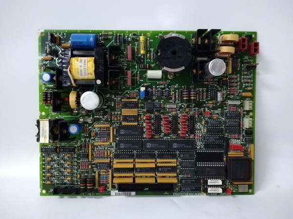
- Physical Interface: Bayonet‑style connectors, J7 power, JK signal interface, on‑board fuses
- Signal Type: MPU sinusoidal speed inputs, flame detector pulse inputs, dry contact trip outputs
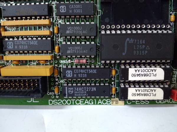
- Processing: Intel 80196 16‑bit microcontroller
- Isolation: 2500 Vrms optical isolation between field inputs and backplane
- Configuration: Berg jumpers for speed threshold scaling, channel selection, and fault masking
- Diagnostics: Front‑panel run, fault, speed, and flame status LEDs
- Environmental: Operating temperature 0°C to +70°C, 5–95% non‑condensing humidity
- Power: Backplane‑fed 5 VDC and 24 VDC from P1 core
- Protection: Three on‑board resettable fuses for field and logic circuits
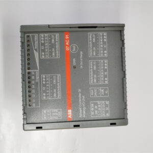
- Form Factor: Standard P1 core PCB footprint
- Weight: 0.145 kg
- Manual Reference: GEH‑6153
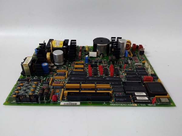
GE DS200TCEAG1A
Customer Value & Operational Benefits
The DS200TCEAG1A operates completely outside the main control and I/O network, delivering a dedicated safety layer that meets IEC 61508‑consistent performance for turbine protection. This independence removes common‑cause failure risks from controller or communication faults, directly reducing the chance of unmanaged overspeed or flame‑loss events.
Local processing cuts speed and flame validation latency to milliseconds, far faster than logic scanned through the main controller. Faster trip action lowers mechanical stress on turbines and combustors, extending component life and reducing maintenance costs over time.
LED status indicators and hardwired jumpers let technicians diagnose faults without software tools. Direct replacement with matching jumper settings restores full operation in minutes, reducing mean time to repair for critical safety circuits.
Field Engineer’s Notes (From the Trenches)
When replacing a DS200TCEAG1A in the P1 core, document every jumper position before removing the old board—incorrect scaling or threshold jumpers will cause either missed trips or false trips that can damage the turbine. Always use twisted‑pair shielded cable for MPU and flame wiring, and ground the shield only at the cabinet end to avoid ground loops that corrupt low‑level speed signals. Never power the board without verifying the three on‑board fuses are intact; backplane voltage spikes can blow fuses silently and leave the safety circuit disabled. The board does not support hot‑swap insertion—always de-energize the P1 core rack before installation to prevent latch‑up in the 80196 microcontroller.
Real-World Applications
- Heavy-Duty Gas Turbine Overspeed Protection
Reads three redundant MPU signals, implements 2-out-of-3 voting logic, and calculates real-time shaft speed. Triggers hardwired emergency fuel shutdown if speed exceeds 110% of rated value, preventing rotor overspeeding and catastrophic failure.
- Combustion Chamber Flame Supervision
Accepts pulse signals from UV flame scanners, validates combustion stability, and initiates immediate fuel isolation if flame is lost or unstable. Prevents unburned fuel buildup and potential explosion in gas turbine combustors.
GE DS200TCEAG1A
High-Frequency Troubleshooting FAQ
A: Yes, it is pin‑for‑pin and function‑compatible. Match all jumper settings from the original unit and no software changes are required. The P1 core backplane interface remains identical across revisions.
A: No LEDs indicate missing P1 core backplane power or a blown on‑board fuse. Check J7 power connector seating, verify 5 VDC and 24 VDC rails, and inspect the three surface‑mount fuses for open circuits. Replace fuses only with identical ratings.
A: False trips typically come from noisy MPU wiring, improper shield grounding, or misconfigured speed‑scaling jumpers. Confirm MPU cable is fully shielded and single‑ended grounded, and re‑verify jumper settings against GEH‑6153 for your turbine’s rated speed.
A: Yes, use designated test jumpers to inject simulated speed and flame signals locally. Never energize field wiring during test mode, and always remove test jumpers before returning the board to active service.