Description
System Architecture & Operational Principle
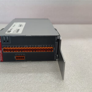
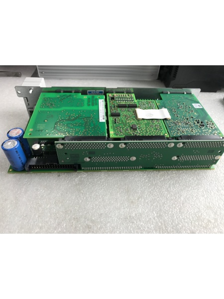
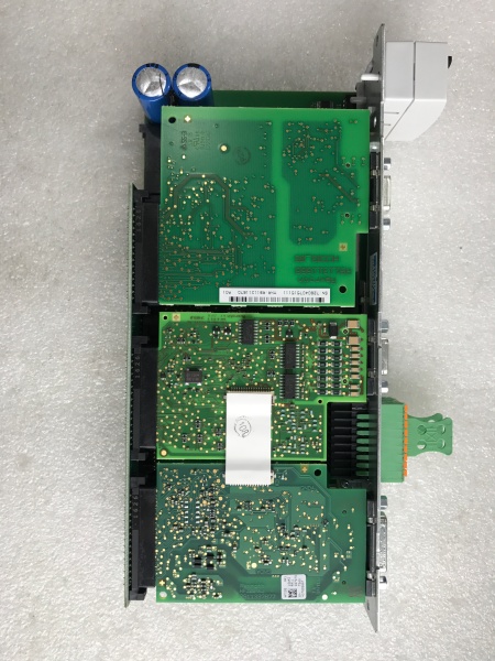
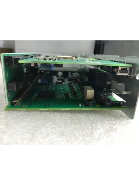
The REXORTH CSH01.1C-PB-ENS-NNN-MEM-S2-S-NN-FW is a modular control section within the IndraDrive drive system, designed to work in tandem with a power section (sold separately) to form a complete servo drive. It connects to the power section via a serial interface (X2 connection point) and communicates with upstream PLCs/controllers using protocols like Profibus, CANopen, or Ethernet.
Upstream Communication: Receives motion commands (speed, position, torque) from a PLC (e.g., Siemens S7-1200) via a fieldbus interface. The control section decodes these commands and converts them into digital signals for processing.
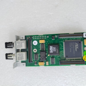
Downstream Operation: Processes the commands using a digital signal processor (DSP) to generate PWM (Pulse-Width Modulation) signals, which are sent to the power section. The power section then converts these signals into high-voltage AC output to drive the servo motor. The control section also monitors motor feedback (via encoders) to adjust the PWM signals in real-time, ensuring precise motion control.
Inherent Advantages:
-
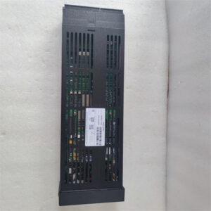
Modular Design: Allows for easy replacement of the control section without disassembling the entire drive, reducing downtime during maintenance.
-
High Precision: Achieves ±0.001° position accuracy, making it suitable for applications requiring tight tolerances (e.g., machine tools).
-
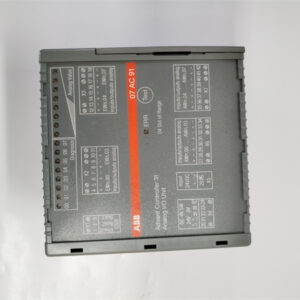
Flexible Integration: Supports multiple communication protocols, enabling seamless integration with legacy PLC systems.

REXROTH CSH01.1C-PB-ENS-NNN-MEM-S2-S-NN-FW
Core Technical Specifications
-
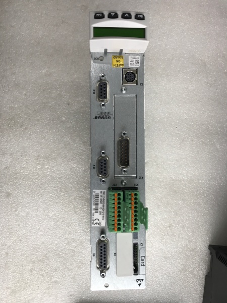
Physical Interface: Serial interface (X2 connection point) for power section integration; screw terminals for input/output connections.
-
Signal Type: PWM (for motor control); analog/digital I/O for auxiliary functions.
-
Input Voltage: 400-480V AC (nominal); 24V DC for control circuit.
-
Output Current: 2-18A (depending on power section configuration).
-
Communication Bus: Profibus, CANopen, Ethernet (supports Modbus TCP/IP).
-
Power Draw: 10-50W (typical, depending on load).
-
Operating Temperature: 0°C to 60°C (32°F to 140°F); storage temperature -40°C to 85°C (-40°F to 185°F).
-
Weight: ~2.5kg (5.5 lbs); dimensions 210mm x 150mm x 70mm (L x W x H).
-
Certifications: CE, UL, RoHS (compliant with international industrial standards).
Customer Value & Operational Benefits
Reduced Downtime with Modular Design
The control section’s plug-and-play design allows technicians to replace a faulty unit in under 30 minutes, minimizing production stoppages. For example, a packaging line using this control section avoided a 2-hour shutdown by swapping the module during a shift change.
Precise Motion Control for Quality Improvement
The ±0.001° position accuracy ensures consistent product quality in applications like CNC machining. A manufacturer reported a 15% reduction in defective parts after upgrading to this control section.
Flexible Integration with Legacy Systems
Support for Profibus and CANopen protocols makes it easy to integrate with older PLCs. A food processing plant used this control section to connect an IndraDrive drive to a Siemens S7-300 PLC, cutting integration time by 40%.
Field Engineer’s Notes (From the Trenches)
When installing the control section, always ground the power supply to prevent electrical noise from affecting the control circuit. I once skipped this step and got erratic motor behavior—took hours to debug.Use shielded cables for encoder feedback to reduce electromagnetic interference (EMI). In a steel mill, unshielded cables caused the control section to lose position feedback, leading to motor stalls.Label the serial interface (X2) connections! Mixing up the TX/RX lines will prevent communication with the power section. I write labels directly on the terminal block with a permanent marker.If the drive throws a “fault F2028” (control deviation too large), check the encoder wiring first. Loose encoder cables are a common cause—tighten the connectors and reset the fault.REXROTH CSH01.1C-PB-ENS-NNN-MEM-S2-S-NN-FW
Real-World Applications
-
Machine Tool Axis ControlThe control section is used in CNC milling machines to control the X/Y/Z axes. It receives position commands from the CNC controller and adjusts the motor speed/torque to achieve precise cuts. The high-precision feedback from the encoder ensures that the tool follows the programmed path accurately.
-
Packaging Line Conveyor ControlA bottling plant uses this control section to regulate the speed of conveyor belts. It communicates with a PLC via Profibus to adjust the belt speed based on bottle density, optimizing throughput and reducing energy consumption.
-
Robotic Arm Joint ControlIn an automotive assembly line, the control section controls the joints of a robotic arm. It processes commands from a central controller to move the arm with precision, ensuring that parts are assembled correctly.
High-Frequency Troubleshooting FAQ
Q: What is the correct way to configure the control section for a new application?
A: Follow these steps: (1) Connect the control section to the power section using the X2 serial cable; (2) Configure the communication protocol (e.g., Profibus) using the IndraWorks software; (3) Set the motor parameters (e.g., pole count, encoder type) in the control section’s menu; (4) Perform a test run to verify motion accuracy. Refer to the IndraDrive user manual for detailed instructions.
Q: How do I diagnose a “no communication” fault between the control section and PLC?
A: Check the following: (1) Ensure the fieldbus cable is securely connected to both the control section and PLC; (2) Verify the communication parameters (e.g., baud rate, node address) match between the devices; (3) Test the fieldbus cable with a multimeter to check for continuity; (4) Replace the control section if the cable is intact but communication still fails.
Q: Can the control section be used with non-IndraDrive power sections?
A: No, the control section uses a proprietary serial interface (X2) that is only compatible with IndraDrive power sections. Using it with a non-IndraDrive power section will result in communication errors.
Q: What is the recommended torque for the terminal screws?
A: 0.8-1.2 N·m (7-10 in-lbs). Over-torquing can strip the terminal threads, while under-torquing can cause loose connections. Use a calibrated torque wrench to ensure proper tightening.
Commercial Availability & Pricing
Please note: The listed price is not the actual final price. It is for reference only and is subject to appropriate negotiation based on current market conditions, quantity, and availability.