Description
Detailed parameter table
| Parameter name | Parameter value |
| Product model | 163179-01 |
| Manufacturer | Bently Nevada |
| Product category | Sensor Extension Cable Assembly |
| Series affiliation | 3500 Machinery Protection System |
| Cable type | Shielded twisted-pair, PTFE insulation |
| Connector type | Male/female micro-D connectors (compatible with 3500 system modules) |
| Length options | 3 meters (standard), custom lengths available up to 30 meters |
| Conductor gauge | 22 AWG |
| Temperature rating | -55°C to +200°C (-67°F to +392°F) |
| Protection features | EMI/RFI shielding, abrasion-resistant jacket |
| Environmental rating | Oil-resistant, chemical-resistant |
| Compatibility | 330180-90-05 proximity sensors, 136188-01 signal input modules, 3500/60 display systems |
| Certification | UL Recognized, CE compliant, RoHS compliant |
| Impedance | 100 ohms ±20% (at 1 MHz) |
| Maximum voltage | 300 V RMS |
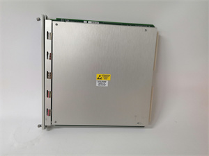
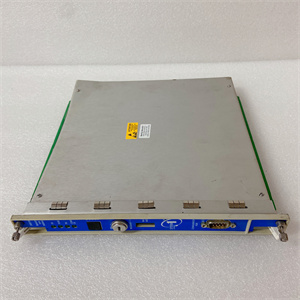
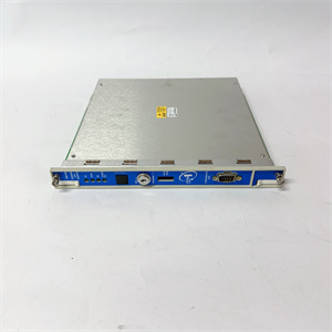
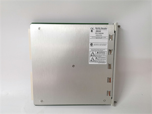
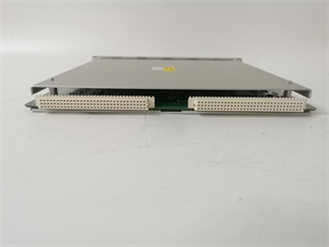
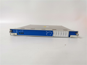
BENTLY 163179-01
Product introduction
The 163179-01 from Bently Nevada is a high-performance sensor extension cable assembly designed specifically for 3500 Machinery Protection Systems. This shielded twisted-pair cable serves as the critical physical link between proximity sensors, vibration transducers, and signal input modules, ensuring reliable transmission of low-level sensor signals in harsh industrial environments. Bently Nevada’s 163179-01 is engineered to preserve signal integrity over extended distances, preventing noise interference and signal degradation that could compromise machinery health measurements displayed on systems like the 3500/60 display module.
Bently Nevada’s 163179-01 addresses the unique challenges of signal transmission in industrial settings, where electrical noise, temperature extremes, and mechanical stress can corrupt sensor data. Its rugged construction and specialized shielding maintain the integrity of measurements from calibrated sensors like the 330180-90-05, ensuring that vibration, position, and displacement data reaches 136188-01 signal input modules without distortion. This cable assembly forms an essential component in the measurement chain, directly impacting the accuracy of data visualized on 3500/60 displays and used for critical protection decisions.
Core advantages and technical highlights
Superior signal integrity: The 163179-01 features precision twisted-pair conductors with 100-ohm impedance matching that minimizes signal reflection and attenuation, even over extended distances. This design ensures that high-frequency vibration components and subtle position changes detected by 330180-90-05 sensors are accurately transmitted to signal input modules, preserving the diagnostic value of the original measurements.
Advanced EMI/RFI protection: The cable incorporates multiple shielding layers—including a tinned copper braid and aluminum foil—that provide 95%+ coverage against electromagnetic and radio frequency interference. This shielding is particularly critical in industrial environments with variable frequency drives, motors, and other noise-generating equipment, preventing interference from corrupting low-level sensor signals.
Extreme environment durability: Constructed with PTFE insulation and an abrasion-resistant outer jacket, the 163179-01 operates reliably across a -55°C to +200°C temperature range. Its oil and chemical resistance makes it suitable for installation in turbine enclosures, compressor skids, and other harsh environments where standard cables would degrade rapidly.
System-optimized connectors: Equipped with micro-D connectors specifically designed for 3500 system components, the cable ensures secure mechanical and electrical connections with 136188-01 signal input modules and sensors. Gold-plated contacts minimize resistance and ensure long-term connection reliability, even with repeated mating cycles during maintenance.
Typical application scenarios
In power generation facilities, the 163179-01 connects 330180-90-05 proximity sensors mounted on turbine bearing housings to 136188-01 signal input modules in control cabinets. These cables route through high-electrical-noise environments near generators and motor control centers, relying on their shielding to maintain signal integrity. The transmitted data ultimately appears on 3500/60 displays in control rooms, where operators monitor shaft vibration and position during turbine startup, shutdown, and normal operation.
Oil and gas processing plants utilize the 163179-01 in compressor train monitoring systems, where cables extend from sensors mounted on rotating equipment to remote monitoring racks. The cable’s chemical resistance withstands exposure to hydrocarbons and cleaning agents, while its high-temperature rating accommodates the elevated ambient temperatures common in compression facilities. Reliable signal transmission ensures accurate vibration data reaches both local 3500/60 displays and remote diagnostic systems.
Manufacturing facilities deploy the 163179-01 to connect sensors on production line machinery to centralized 3500 monitoring systems. The cables route through factory floors, navigating around moving equipment and withstanding occasional contact and abrasion thanks to their rugged jacket. In these applications, the cables preserve measurement integrity for motor vibration, pump alignment, and gearbox health data—critical information displayed on 3500/60 modules for operators and maintenance teams.
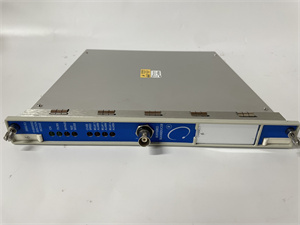
BENTLY 163179-01
Related model recommendations
330180-90-05 (Bently Nevada): Proximity sensor directly connected by 163179-01 cables.
136188-01 (Bently Nevada): Signal input module receiving signals via 163179-01.
3500/60 (Bently Nevada): Display module visualizing data transmitted through 163179-01.
3500/05-01-02-00-00-01 (Bently Nevada): Power supply for systems using 163179-01 cables.
330130-080-00-00 (Bently Nevada): Calibration fixture used with systems incorporating 163179-01.
163179-02 (Bently Nevada): 5-meter variant of the 163179-01 cable assembly.
330108-91-05 (Bently Nevada): Complementary extension cable for legacy system integration.
3500/20 (Bently Nevada): System rack housing modules connected by 163179-01 cables.
Installation, handling and maintenance instructions
Installation preparation: Before installing 163179-01 cables, verify compatibility with connected sensors (typically 330180-90-05) and 136188-01 modules. Inspect cables for shipping damage, checking for jacket abrasions, connector bent pins, or shield damage. Required tools include connector torque wrenches, cable ties, and appropriate mounting hardware. Plan cable routes to avoid high-noise areas (transformers, VFDs) and mechanical stress points where possible.
Mounting and routing: Route 163179-01 cables separately from power cables to minimize electromagnetic interference, maintaining at least 30cm separation where parallel routing is necessary. Use proper cable supports every 30-50cm to prevent excessive strain on connectors. When bending, maintain a minimum bend radius of 5cm (2 inches) to avoid conductor damage. Ensure cables are not stretched or compressed during installation, which could alter impedance characteristics.
Connector installation: Mate connectors carefully, ensuring proper alignment before applying pressure to avoid pin damage. Torque connectors to specified values (typically 0.5 Nm) using a calibrated torque wrench to ensure proper electrical contact without damaging threads. Verify all connector pins are intact after mating. For outdoor or wet locations, apply approved sealing compounds to connector interfaces as specified in installation guidelines.
Maintenance suggestions: Include 163179-01 cables in quarterly visual inspections, checking for jacket damage, connector corrosion, and secure mounting. During scheduled shutdowns, disconnect and reconnect connectors to ensure they maintain proper contact. Clean connectors with approved electronic contact cleaner if contamination is visible. Verify cable continuity using a multimeter if signal quality issues are detected on 3500/60 displays. Replace cables immediately if shielding damage, conductor exposure, or connector damage is 发现.
Service and guarantee commitment
Bently Nevada provides the 163179-01 with a 24-month warranty covering manufacturing defects and material failures under normal operating conditions. Our technical support team offers guidance on proper installation practices, cable routing, and compatibility verification with 330180-90-05 sensors, 136188-01 modules, and 3500/60 display systems.
We offer application engineering support to determine optimal cable lengths and routing strategies for specific monitoring configurations, ensuring maximum signal integrity. Beyond the warranty period, our service agreements include cable testing services and expedited replacement options to minimize downtime. Bently Nevada’s commitment to quality ensures the 163179-01 delivers reliable signal transmission throughout its operational lifecycle, backed by our global network of service professionals and application engineers.