Description
System Architecture & Operational Principle
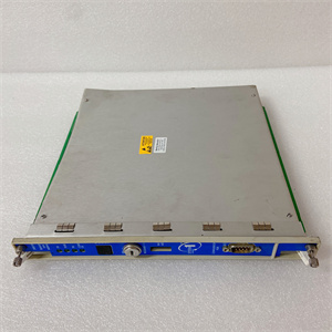
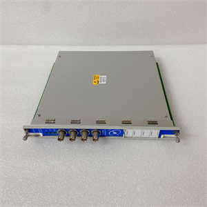
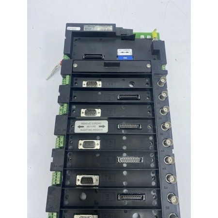
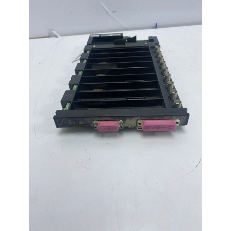
The Bently 1701/05 is a terminal base module within the Bently Nevada 1701 FieldMonitor™ Series, a field-mounted, distributed I/O architecture designed for Level 1 (Device) or Level 2 (Control) of the Purdue Model in industrial automation. It resides in the field (e.g., on a machine’s guard or control cabinet) and acts as the bridge between transducers (e.g., proximity probes, accelerometers) and 1701 FieldMonitor™ Series modules (e.g., 170180-XX-XX Transducer I/O Modules).
Upstream Communication
Receives raw signals from transducers (e.g., proximity probes measuring shaft vibration, accelerometers measuring casing vibration) via wired connections to the terminal base’s input terminals.
Downstream Communication
Transmits processed signals from transducers to 1701 FieldMonitor™ Series modules (e.g., 170180-XX-XX) for data acquisition and analysis. These modules then send data to higher-level systems (e.g., DCS, SCADA) for monitoring or control.
Operational Advantages
-
Distributed Architecture: Reduces installation costs by eliminating the need for long cable runs from transducers to a central rack.
-
Field Mounting: Designed for harsh industrial environments (e.g., dust, moisture), with a rugged design that withstands vibration and temperature extremes.
-
Modularity: Supports multiple 1701 FieldMonitor™ Series modules (e.g., transducer I/O, seismic input monitors), allowing flexible configuration for different machinery protection needs.
Core Technical Specifications
|
Attribute
|
Specification
|
|---|---|
|
Module Type
|
Terminal Base (Field-Mounted)
|
|
Compatibility
|
1701 FieldMonitor™ Series modules (e.g., 170180-XX-XX, 1701/15-01)
|
|
Input Capacity
|
Up to 2 transducer inputs per module
|
|
Hazardous Area Support
|
Compatible with 1701/06-01 Isolator Terminal Base (Division 2/Zone 2 for monitors)
|
|
Mounting
|
Field-mounted (on machine guard or control cabinet)
|
|
Dimensions
|
Approx. 241 mm × 146 mm × 64 mm (9.5 in × 5.75 in × 2.5 in) (from 1701 series standard)
|
|
Weight
|
Approx. 0.68 kg (1.5 lbs) (from 1701 series standard)
|
|
Certifications
|
CE, UL, CSA (from 1701 series standard)
|
BENTLY 1701/05
Customer Value & Operational Benefits
Reduced Installation Costs
The 1701/05’s distributed architecture eliminates the need for long cable runs from transducers to a central rack, reducing installation time and material costs. For example, a power plant using the 1701/05 to monitor a steam turbine can install the terminal base on the turbine’s guard, reducing cable length by 50% compared to a rack-mounted system.
Enhanced Reliability
Field-mounted terminal bases are less susceptible to cable damage from vibration or environmental factors (e.g., dust, moisture) than rack-mounted systems. This reduces the risk of signal loss or equipment damage, improving overall system reliability.
Flexible Configuration
The 1701/05 supports multiple 1701 FieldMonitor™ Series modules, allowing facilities to customize their machinery protection system to meet specific needs. For example, a refinery can use the 1701/05 with a 170180-XX-XX Transducer I/O Module to monitor compressor vibration and a 1701/25-01 Seismic Input Monitor to monitor pump casing vibration.
Field Engineer’s Notes (From the Trenches)
When installing the 1701/05, always verify the mounting surface—the terminal base must be mounted on a flat, rigid surface to prevent vibration-induced loosening. I once saw a site where a contractor mounted the base on a thin sheet metal panel, resulting in loose connections and intermittent signal loss. Use a drill and screws to secure the base to a solid surface (e.g., machine guard).Another gotcha: check the terminal block connections—loose wires are a common cause of signal loss. Use a torque wrench to tighten the terminal screws to the manufacturer’s specification (typically 0.5–1.0 N·m) to ensure a secure connection.If the terminal base’s “POWER” LED is off, check the power supply—the 1701/05 requires 24 VDC from a 1701/10-01 Power Supply. Use a multimeter to measure the voltage at the terminal block to confirm power is reaching the base.
Real-World Applications
-
Power Generation: Steam Turbine MonitoringA coal-fired power plant uses the 1701/05 to mount a 170180-XX-XX Transducer I/O Module on a steam turbine’s guard. The module receives signals from two proximity probes (measuring shaft vibration) and transmits data to a 1701/22-01 FieldMonitor Management Interface Module, which sends data to the plant’s DCS for monitoring.
-
Oil & Gas: Centrifugal Compressor ProtectionAn offshore oil platform uses the 1701/05 to mount a 1701/25-01 Seismic Input Monitor on a centrifugal compressor’s casing. The monitor receives signals from two accelerometers (measuring casing vibration) and triggers an alarm if vibration exceeds the trip threshold, preventing damage to the compressor.

Bently 1701/05
High-Frequency Troubleshooting FAQ
Q: What is the Bently 1701/05 used for?
A: The 1701/05 is a terminal base module in the 1701 FieldMonitor™ Series, used to mount and connect transducer I/O modules (e.g., 170180-XX-XX) for field-mounted machinery protection systems. It provides mechanical stability and electrical connectivity for transducers (e.g., proximity probes, accelerometers).
Q: Can the 1701/05 be used with non-1701 FieldMonitor™ Series modules?
A: No, the 1701/05 is designed exclusively for 1701 FieldMonitor™ Series modules. Non-1701 modules may not fit the terminal base or communicate properly with the system.
Q: How do I install the 1701/05?
A: Follow these steps:
-
Select a Mounting Surface: Choose a flat, rigid surface (e.g., machine guard) that is protected from dust and moisture.
-
Mark the Mounting Holes: Use the terminal base’s template to mark the mounting holes on the surface.
-
Drill the Holes: Drill pilot holes for the screws (use a drill bit slightly smaller than the screw diameter).
-
Secure the Base: Use screws to attach the terminal base to the surface (tighten to the manufacturer’s specification).
-
Connect the Transducers: Wire the transducers to the terminal base’s input terminals (follow the wiring diagram in the 1701 FieldMonitor™ Series manual).
Q: Why is the 1701/05’s “POWER” LED off?
A: Check three things first:
-
Power Supply: Ensure the 1701/10-01 Power Supply is turned on and supplying 24 VDC.
-
Terminal Block Connections: Verify that the power wires are securely connected to the terminal base’s power terminals.
-
Fuse: Check the terminal base’s internal fuse (if equipped) for continuity (replace if blown).
Commercial Availability & Pricing
Please note: The listed price is not the actual final price. It is for reference only and is subject to appropriate negotiation based on current market conditions, quantity, and availability.