

Description
System Architecture & Operational Principle
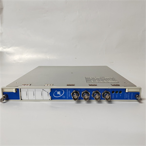
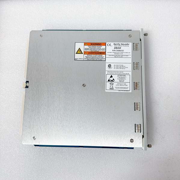
The Bently 288055-01 is a Transient Data Interface (TDI) module within the Bently Nevada 3500 Series Machinery Protection System, designed for Level 1 (Device) or Level 2 (Control) of the Purdue Model in industrial automation. It resides in Slot 1 of the 3500 rack (adjacent to the power supply module) and serves as the bridge between 3500 Series monitor modules (e.g., 3500/40M vibration monitors, 3500/45 position monitors) and external analysis tools (e.g., Bently’s System 1 condition monitoring software).
Upstream Communication
Receives raw data from all 3500 Series monitor modules via the rack’s backplane. This data includes:
-
Steady-State Values: Conventional operating parameters (e.g., vibration amplitude, shaft position, temperature).
-
Transient Dynamic Data: High-resolution waveforms (e.g., vibration during startup/shutdown,冲击 events, trip conditions).
Downstream Communication
Transmits processed data to external systems using standard industrial protocols:
-
Ethernet: 10/100Base-TX (copper) or 100Base-FX (fiber-optic) for high-speed data transfer to System 1 or plant DCS/SCADA systems.
-
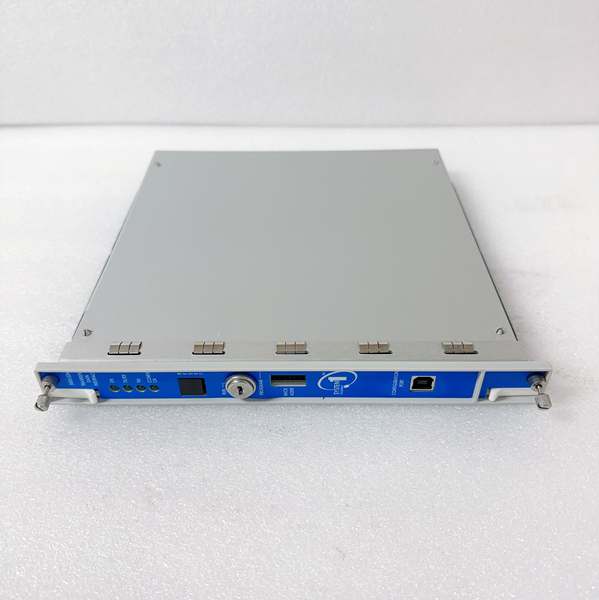
USB-B: Front-panel interface for configuration and debugging via a PC.
Operational Advantages
-
High-Speed Data Capture: Supports high-frequency transient acquisition (frequency depends on front-end sensors and system configuration), enabling detailed analysis of machinery behavior during critical events (e.g., turbine trip).
-
Seamless Integration: Works with Bently’s System 1 software for predictive maintenance, condition monitoring, and fault diagnosis.
-
Hot-Swappable Design: Can be replaced without shutting down the 3500 system, minimizing downtime during maintenance.

BENTLY 288055-01
Core Technical Specifications
|
Attribute
|
Specification
|
|---|---|
|
Communication Interfaces
|
10/100Base-TX Ethernet (RJ-45); 100Base-FX fiber-optic; USB-B (front panel)
|
|
Data Types
|
Steady-state values (amplitude, phase); transient waveforms (vibration,冲击)
|
|
Power Supply
|
24 VDC (from 3500 rack; ~10.5 W typical power consumption)
|
|
Operating Temperature
|
-30°C to +65°C (-22°F to 149°F)
|
|
Storage Temperature
|
-40°C to +85°C (-40°F to 185°F)
|
|
Dimensions (W×H×D)
|
241.3 mm × 24.4 mm × 241.8 mm (9.50 in × 0.96 in × 9.52 in)
|
|
Weight
|
0.91 kg (2.0 lbs)
|
|
Certifications
|
CE, UL, CSA, ATEX (hazardous locations)
|
|
Compatibility
|
3500 Series racks; works with 3500/20 Rack Interface Module (RIM) for communication
|
Customer Value & Operational Benefits
Enhanced Machinery Diagnosis
The 288055-01’s ability to capture high-resolution transient data enables early detection of incipient faults (e.g., bearing wear, rotor imbalance). For example, a power plant using the module to monitor a steam turbine can record vibration waveforms during startup and use System 1 to analyze the data, identifying potential issues before they cause a failure.
Seamless Integration with System 1
The module is optimized for communication with Bently’s System 1 software, allowing engineers to perform advanced diagnostics (e.g., spectral analysis, trend forecasting) on captured data. This integration enables predictive maintenance, reducing unplanned downtime and extending machinery life.
Reduced Maintenance Costs
The hot-swappable design allows technicians to replace a faulty module in minutes without interrupting the 3500 system’s operation. This minimizes labor costs and production losses—critical for facilities with tight maintenance budgets.
Compliance with Industry Standards
The module complies with API 670 (American Petroleum Institute standard for machinery protection systems), ensuring it meets the rigorous requirements of industries like oil & gas, power generation, and chemical processing.
Field Engineer’s Notes (From the Trenches)
When installing the 288055-01, always verify the slot position—the module must be installed in Slot 1 of the 3500 rack (adjacent to the power supply). I once saw a site where a contractor installed it in the wrong slot, resulting in no communication with the monitor modules. Use the 3500 Rack Layout Guide to confirm the correct slot.Another gotcha: check the Ethernet cable type—if using fiber-optic, ensure the cable is compatible with 100Base-FX (e.g., SC connectors). I’ve fixed countless “no communication” faults by replacing a mismatched fiber cable.If the module’s “TX/RX” LED is not blinking, check the System 1 configuration—ensure the software is set to receive data from the correct IP address. Use the 3500 Configuration Software to verify the module’s IP settings.BENTLY 288055-01
Real-World Applications
-
Power Generation: Steam Turbine MonitoringA coal-fired power plant uses the 288055-01 to collect vibration data from a 3500/40M monitor module. The module transmits the data to System 1, which analyzes the waveforms and detects a bearing wear fault. The plant schedules a maintenance shutdown before the bearing fails, avoiding a costly unplanned outage.
-
Oil & Gas: Centrifugal Compressor ProtectionAn offshore oil platform uses the 288055-01 to capture transient data from a 3500/45 position monitor. During a compressor trip, the module records the vibration waveform, which is later analyzed to determine the cause of the trip (e.g., surge event). This data helps the platform optimize the compressor’s operating parameters, reducing future trip events.
High-Frequency Troubleshooting FAQ
Q: What does the “OK” LED indicate on the 288055-01?
A: The green “OK” LED indicates that the module is receiving power from the 3500 rack and communicating with the monitor modules. If it’s off, check the rack’s power supply (3500/15) and the module’s connection to the backplane.
Q: Can the 288055-01 be used with non-Bently systems?
A: No, the module is designed exclusively for Bently Nevada 3500 Series systems. It relies on the 3500 rack’s backplane for power and communication, so using it with non-Bently systems will result in compatibility issues.
Q: How do I configure the Ethernet settings?
A: Use the 3500 Configuration Software to set the module’s IP address, subnet mask, and gateway. Ensure the settings match the plant’s network configuration.
Q: Why is the 288055-01 not transmitting data to System 1?
A: Check three things first:
-
Ethernet Cable: Ensure the cable is securely connected to the module and the System 1 workstation.
-
IP Address: Verify that the module’s IP address is correct and within the System 1 workstation’s subnet.
-
System 1 Configuration: Ensure the software is set to receive data from the correct IP address.
Commercial Availability & Pricing
Please note: The listed price is not the actual final price. It is for reference only and is subject to appropriate negotiation based on current market conditions, quantity, and availability.