

Description
System Architecture & Operational Principle
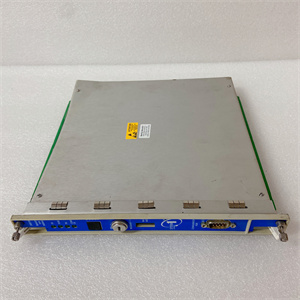
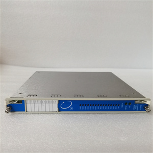
The Bently 3500/45-09-GCN is a 4-channel position/expansion difference monitor module within the Bently Nevada 3500 Series Machinery Protection System, designed for Level 1 (Device) or Level 2 (Control) of the Purdue Model in industrial automation. It resides in the 3500 Series rack (typically in Slots 3–14, adjacent to relay or communication modules) and serves as the bridge between sensors (e.g., proximity probes, LVDTs) and higher-level systems (e.g., DCS, SCADA).
Upstream Communication
Receives raw signals from up to four sensors via the 3500 rack’s backplane. These sensors measure:
-
Axial (Thrust) Position: Shaft displacement along the axis (critical for detecting rotor imbalance or bearing wear).
-
Differential Expansion: Difference in expansion between the rotor and stator (important for thermal stability in turbines).
-
Case Expansion: Expansion of the machine casing (monitored on Channels 3/4 only).
-
Valve Position: Position of control valves (for process optimization).
Downstream Communication
Transmits processed data (e.g., peak position, expansion difference) to:
-
3500 Series Relay Modules (e.g., 3500/32): Trigger alarms or shutdowns if parameters exceed thresholds.
-
External Systems (e.g., Emerson DeltaV, Siemens S7-1500): Send real-time data for monitoring or analytics via Modbus TCP/IP or proprietary protocols.
Operational Advantages
-
High Versatility: Supports multiple sensor types (proximity, LVDT, RPT) and measurement functions (axial position, differential expansion), making it suitable for diverse machinery (turbines, compressors, pumps).
-
Hot-Swappable Design: Can be replaced without shutting down the 3500 system, minimizing downtime during maintenance.
-
User-Programmable Logic: Each channel can be configured via 3500 Rack Configuration Software to set alarm thresholds (Alert/Danger) and delays, adapting to specific application needs.

BENTLEY 330130-080-00-CN
Core Technical Specifications
|
Attribute
|
Specification
|
|---|---|
|
Channel Count
|
4 independent channels
|
|
Input Types
|
Proximity probes, RPTs, DC/AC LVDTs, rotary potentiometers
|
|
Measurement Functions
|
Axial position, differential expansion (standard/non-standard/dual ramp), case expansion (CH3/4), valve position
|
|
Alarm Configuration
|
User-programmable Alert/Danger thresholds; per-channel logic (AND/OR)
|
|
Power Supply
|
From 3500 rack (24 VDC)
|
|
Operating Temperature
|
-30°C to +65°C (-22°F to 149°F)
|
|
Storage Temperature
|
-40°C to +85°C (-40°F to 185°F)
|
|
Dimensions (H×W×D)
|
241.3 mm × 24.4 mm × 241.8 mm (9.50 in × 0.96 in × 9.52 in)
|
|
Weight
|
0.91 kg (2.0 lbs)
|
|
Certifications
|
CE, UL, CSA, ATEX (hazardous locations)
|
|
Compatibility
|
3500 Series rack (requires 3500/20 RIM for communication)
|
Customer Value & Operational Benefits
Enhanced Machinery Protection
The 3500/45-09-GCN’s ability to monitor axial position and differential expansion enables early detection of incipient faults (e.g., rotor imbalance, bearing wear), preventing catastrophic failures and reducing unplanned downtime. For example, a power plant using the module to monitor a steam turbine can detect abnormal axial displacement and shut down the turbine before damage occurs.
Seamless Integration with 3500 Series
As a core component of the 3500 Series, the 3500/45-09-GCN integrates seamlessly with other 3500 modules (e.g., 3500/32 relays, 3500/92 communication gateway). This eliminates the need for custom wiring or protocol converters, reducing integration time and costs.
Reduced Maintenance Costs
The hot-swappable design allows technicians to replace a faulty module in minutes without interrupting the 3500 system’s operation. This minimizes labor costs and production losses—critical for facilities with tight maintenance budgets.
Compliance with Industry Standards
The module complies with API 670 (American Petroleum Institute standard for machinery protection systems), ensuring it meets the rigorous requirements of industries like oil & gas, power generation, and chemical processing.

BENTLEY 330130-080-00-CN
Field Engineer’s Notes (From the Trenches)
When installing the 3500/45-09-GCN, always verify the sensor type and gap—the module supports multiple sensor types, but each requires a specific gap setting (e.g., 0.5–1.0 mm for proximity probes). An incorrect gap will cause the module to misinterpret signals, leading to false alarms. I once saw a site where a contractor set the gap too wide, resulting in missed faults and a damaged turbine.Another gotcha: ground the module properly—the 3500 system’s IP65 rating requires a proper ground connection to protect against electric shock and EMI. I’ve fixed countless “ghost” faults (e.g., random communication drops) by ensuring the module’s ground wire is connected to the cabinet’s earth ground.If the module’s “FAULT” LED is red, check the sensor wiring—loose or reversed wires are a common cause of faults. Use a multimeter to test for continuity between the sensor and the module’s input terminals. Also, ensure the sensor’s shield is grounded to the 3500 rack’s earth ground to reduce EMI.
Real-World Applications
-
Power Generation: Steam Turbine MonitoringA coal-fired power plant uses the 3500/45-09-GCN to monitor a steam turbine’s axial position. The module processes signals from two proximity probes (installed on the turbine’s shaft) and transmits data to a Siemens S7-1500 PLC via Modbus TCP/IP. The PLC uses this data to adjust the turbine’s inlet guide vanes, preventing surge events.
-
Oil & Gas: Centrifugal Compressor ProtectionAn offshore oil platform uses the 3500/45-09-GCN to monitor a centrifugal compressor’s differential expansion. The module receives signals from two LVDTs (installed on the compressor’s rotor and stator) and triggers an alarm if the expansion difference exceeds the trip threshold (e.g., 0.5 inches), preventing damage to the compressor.
High-Frequency Troubleshooting FAQ
Q: What does the “FAULT” LED indicate on the 3500/45-09-GCN?
A: The red “FAULT” LED indicates a critical error, such as:
-
Sensor failure (e.g., broken wire, faulty probe).
-
Input signal out of range (e.g., too high or too low voltage).
-
Module hardware failure (e.g., corrupted firmware, damaged components).Check the 3500 Rack Configuration Software for detailed fault codes and follow the manufacturer’s troubleshooting steps.
Q: Can the 3500/45-09-GCN be used with non-Bently sensors?
A: No, the module is designed to work exclusively with Bently Nevada sensors (e.g., 3300 XL proximity probes, 7500 LVDTs). Non-Bently sensors may not meet the required signal specifications, leading to inaccurate measurements or module failure.
Q: How do I program the alarm thresholds?
A: Use the 3500 Rack Configuration Software to select the module and configure each channel’s alarm thresholds (Alert/Danger). You can also set the alarm delay (1–60 seconds for Alert, 0.5–60 seconds for Danger) to prevent false trips from transient anomalies.
Q: Why is the 3500/45-09-GCN not transmitting data to the DCS?
A: Check three things first:
-
Communication Gateway: Ensure the 3500/92 Communication Gateway is properly configured and connected to the DCS.
-
Protocol Settings: Verify that the DCS is configured for the correct protocol (e.g., Modbus TCP/IP) and that the module’s IP address is correct.
-
Module Status: Check the module’s LED indicators—if the “FAULT” LED is on, resolve the internal fault before proceeding.
Commercial Availability & Pricing
Please note: The listed price is not the actual final price. It is for reference only and is subject to appropriate negotiation based on current market conditions, quantity, and availability.