Description
Detailed parameter table
| Parameter name | Parameter value |
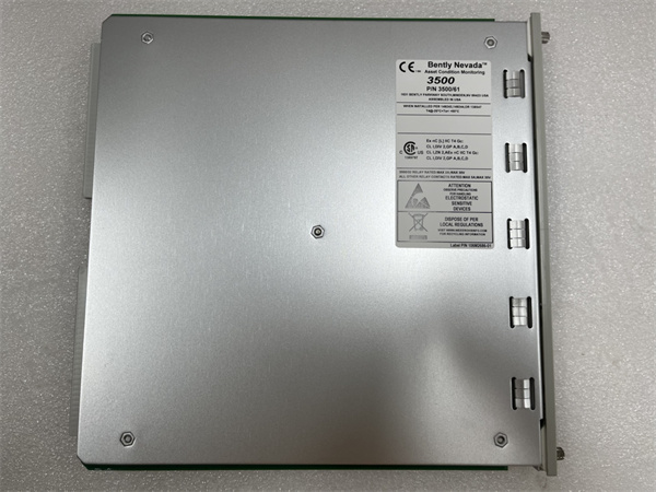
| Product model | 3500/61 |
| Manufacturer | Bently Nevada |
| Product category | Machinery Protection System Display Module |
| Series affiliation | 3500 Machinery Protection System |
| Display type | 10.4-inch color LCD (800×600 resolution) |
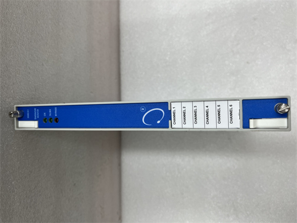
| Input channels | Supports up to 256 monitored parameters |
| Data refresh rate | 1-second minimum refresh interval |
| Alarm indicators | Multi-color LED status indicators (per channel), audible alarm capability |
| Communication ports | 2× Ethernet (10/100BASE-T), 1× RS-232 |
| Protocols supported | Modbus TCP/IP, Bently Nevada proprietary protocol |
| Operating voltage | 5 VDC, ±15 VDC (powered by 3500/05-01-02-00-00-01 power supply) |
| Power consumption | 15 W typical, 20 W maximum |
| Operating temperature | 0°C to +55°C (32°F to +131°F) |
| Storage temperature | -40°C to +70°C (-40°F to +158°F) |
| Form factor | 3500 system rack mount (2 slot width) |
| Dimensions | 266 mm (H) × 72 mm (W) × 229 mm (D) (10.5″ × 2.8″ × 9.0″) |
| Protection features | Password protection, audit trail logging, redundant power support |
| Compatibility | 163179-02 extension cables, 3500/70M monitors, 3500/34 gateways |
| Certification | UL, CE, RoHS compliant, IEC 61010-1 approved |
| User interface | Touchscreen and membrane keypad operation |
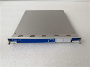
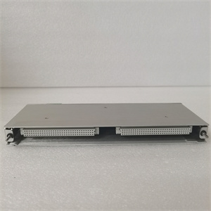
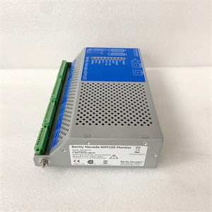
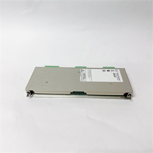
BENTLY 3500/61
Product introduction
The 3500/61 from Bently Nevada is a high-performance display module designed as the primary human-machine interface (HMI) for 3500 Machinery Protection Systems. This rack-mount display serves as the central visualization hub for critical machinery health data, providing operators with real-time access to vibration measurements, position readings, and alarm statuses from connected sensors and monitoring modules. Bently Nevada’s 3500/61 acts as the information nexus of the 3500 ecosystem, aggregating data from systems connected via 163179-02 extension cables and 3500/70M monitors, then presenting it in intuitive formats that enable quick assessment of machinery condition.
Bently Nevada’s 3500/61 addresses the need for clear, actionable machinery health information in industrial control environments. Its high-resolution display and configurable interfaces transform raw sensor data into meaningful visualizations—including trend graphs, alarm lists, and diagnostic plots—that help operators distinguish between normal variations and critical conditions. By consolidating information from across the protection system, this module ensures that critical alerts from components like 3500/70M monitors are immediately visible, supporting timely decision-making that prevents machinery damage and unplanned downtime.
Core advantages and technical highlights
Comprehensive data visualization: The 3500/61 features a 10.4-inch color LCD display with 800×600 resolution that presents complex machinery data in multiple formats—including digital readouts, bar graphs, trend plots, and alarm annunciators. This versatility allows operators to quickly assess both real-time conditions and historical trends, with customizable screen layouts tailored to specific machinery types or operational preferences.
Centralized alarm management: Equipped with multi-color LED indicators and audible alarm capabilities, the module provides immediate visual and auditory notification of machinery issues. Alarms are prioritized by severity (warning, alarm, danger) and include detailed context such as affected parameter, timestamp, and current value—critical for distinguishing between routine notifications and emergency conditions requiring immediate action.
Seamless system integration: The 3500/61 connects directly to the 3500 system backplane and via Ethernet to 3500/34 communication gateways, enabling it to aggregate data from all system components. This integration includes compatibility with sensor networks using 163179-02 extension cables, ensuring measurements from remote sensors appear in real-time alongside data from local monitoring modules like the 3500/70M.
Enhanced operational security: Incorporating password-protected access levels, audit trail logging, and configuration lockout features, the module ensures that only authorized personnel can modify critical protection parameters. This security framework prevents accidental configuration changes while maintaining a complete record of all system modifications and alarm responses.
Typical application scenarios
In power generation control rooms, the 3500/61 serves as the primary monitoring interface for turbine and generator protection systems. It displays real-time vibration data from 133396-01 accelerometers connected via 163179-02 cables, alongside temperature and pressure readings from complementary sensors. Operators use its trend analysis tools to compare current performance against historical baselines, identifying subtle degradation patterns that indicate upcoming maintenance needs. Critical alarms from 3500/70M monitors trigger immediate visual alerts on the display, enabling rapid response to potential machinery issues.
Oil and gas processing facilities deploy the 3500/61 in compressor control stations, where it consolidates data from multiple reciprocating and centrifugal compressors. The module’s customizable screens display vibration spectra, peak-to-peak values, and bearing condition indicators for each machine, with color-coded status indicators highlighting any units requiring attention. Its integration with 3500/34 gateways allows operators to access the same information remotely, supporting both on-site and off-site monitoring of critical compression equipment.
Manufacturing plants utilize the 3500/61 in centralized maintenance control centers, where it provides a consolidated view of machinery health across production lines. The display shows vibration and temperature data from motors, pumps, and gearboxes connected through 163179-02 cables, with configurable dashboards tailored to different production areas. Maintenance teams use its historical data storage and export capabilities to generate equipment health reports, supporting both reactive troubleshooting and proactive maintenance planning.
BENTLY 3500/61
Related model recommendations
163179-02 (Bently Nevada): Extension cable transmitting sensor data to systems monitored by 3500/61.
3500/70M (Bently Nevada): Recip monitor whose data is displayed on 3500/61.
3500/34 (Bently Nevada): Communication gateway providing data to 3500/61 from distributed systems.
3500/05-01-02-00-00-01 (Bently Nevada): Power supply for the 3500/61 module.
3500/20 (Bently Nevada): System rack housing the 3500/61 display module.
133396-01 (Bently Nevada): Accelerometer whose measurements appear on 3500/61.
125680-01 (Bently Nevada): Vibration transmitter sending data visualized on 3500/61.
330130-080-00-00 (Bently Nevada): Calibration fixture ensuring data accuracy for 3500/61 displays.
Installation, configuration and maintenance instructions
Installation preparation: Before installing the 3500/61, verify compatibility with the target 3500/20 rack and ensure the system firmware supports the display module. Confirm the 3500/05-01-02-00-00-01 power supply can accommodate the additional load. Required tools include a screwdriver set, torque wrench, and laptop with 3500 configuration software. Inspect the module for shipping damage, particularly checking the display screen, connectors, and front panel controls.
Mounting and wiring: Insert the 3500/61 into two adjacent slots in the 3500/20 rack, securing it with front panel screws torqued to specified values. Power is supplied through the rack backplane, eliminating external power wiring requirements. Connect Ethernet cables to the network ports for communication with 3500/34 gateways or other networked devices, using shielded Cat5e/6 cables with proper grounding.
Configuration procedures: Power on the 3500 system and establish communication with the 3500/61 using configuration software. Define the display parameters, mapping vibration data, temperatures, and other measurements from connected modules like the 3500/70M. Configure alarm thresholds, visual indicators, and audible alerts according to machinery protection requirements. Set up user access levels and security parameters to control configuration changes and data access.
Maintenance suggestions: Include the 3500/61 in monthly system inspections, verifying display clarity, LED functionality, and touchscreen responsiveness. Check network connectivity and data synchronization with remote sensors connected via 163179-02 cables. Back up configuration settings regularly to preserve custom display layouts and alarm configurations. Clean the display screen with a soft, lint-free cloth and approved cleaning solution—avoid harsh chemicals that could damage the screen coating. During scheduled maintenance, verify firmware compatibility with other system components and update if necessary to ensure optimal performance.
Service and guarantee commitment
Bently Nevada provides the 3500/61 with a 36-month warranty covering manufacturing defects and performance issues under normal operating conditions, including display functionality, communication capabilities, and alarm indicators. Our technical support team offers expert guidance on configuration, screen customization, and integration with 163179-02 cable systems, 3500/70M monitors, and 3500/34 communication gateways.
We offer specialized training on display module operation, alarm management, and advanced visualization features specific to the 3500/61. Beyond the warranty period, our service agreements include technical support, configuration assistance, and expedited replacement services to minimize downtime. Bently Nevada’s commitment to quality ensures the 3500/61 delivers reliable information visualization throughout its operational lifecycle, backed by our global network of service professionals and application engineers.