
Description
System Architecture & Operational Principle
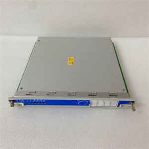
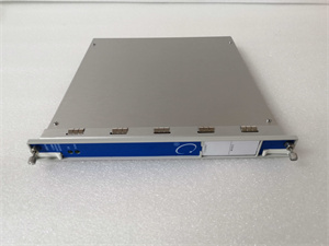
The Bently Nevada 177230-01-02-05 is a seismic transmitter designed for Level 1 (Device) or Level 2 (Control) of the Purdue Model in industrial automation. It resides in the field (e.g., on a machine’s guard or control cabinet) and serves as the bridge between vibration sensors (e.g., accelerometers, proximity probes) and higher-level systems (e.g., DCS, SCADA, PLCs).
Upstream Communication
Receives raw vibration signals from sensors installed on critical machinery components (e.g., bearing housings, motor windings, turbine casings). These signals represent mechanical vibration, which is a key indicator of machinery health.
Downstream Communication
Transmits processed vibration data to external systems using a 4–20 mA current loop (standard for industrial instrumentation). This signal is proportional to the vibration amplitude, allowing operators to monitor machinery condition in real time. The transmitter also supports RS-485/Modbus RTU for digital communication, enabling integration with modern control systems.
Operational Advantages
-
High Precision: Measures vibration with ±0.1% full-scale accuracy, critical for detecting incipient faults (e.g., bearing wear, rotor imbalance).
-
Hazardous Area Certification: Compliant with CSA/ATEX/IECEx standards, making it suitable for use in explosive atmospheres (e.g., oil & gas platforms, chemical plants).
-
Hot-Swappable Design: Can be replaced without shutting down the system, minimizing downtime during maintenance.

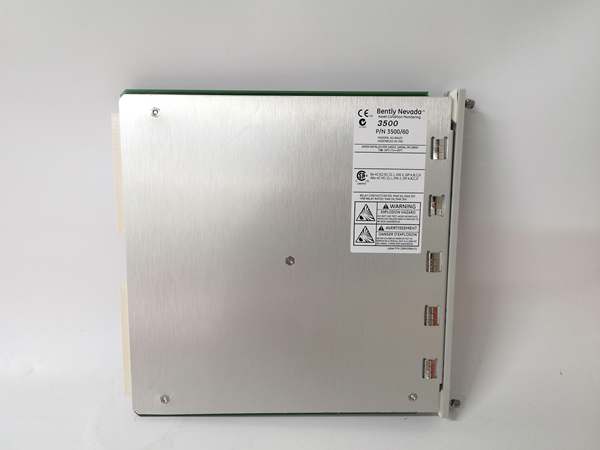
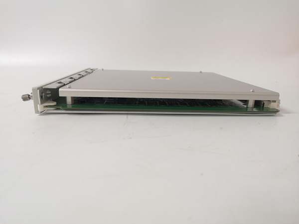
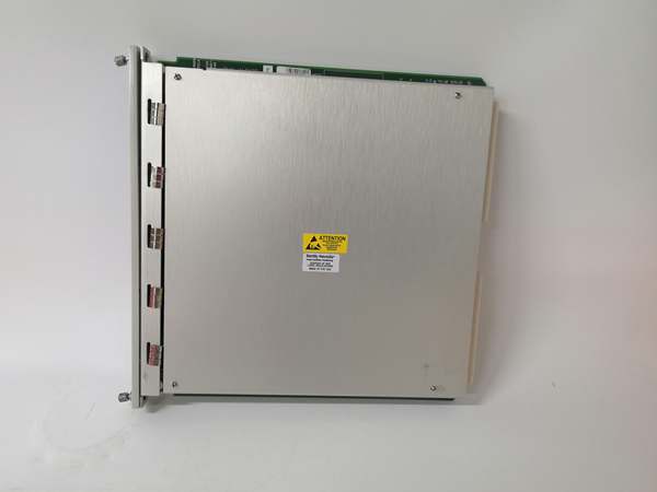
Bently 3500/60 163179-01
Core Technical Specifications
|
Attribute
|
Specification
|
|---|---|
|
Measurement Range
|
0–25.4 mm/s (0–1.0 in/s) ± 10%
|
|
Frequency Response
|
3 Hz–1 kHz (180–60 kcps) ± 10%
|
|
Output Signal
|
4–20 mA current loop (proportional to vibration amplitude)
|
|
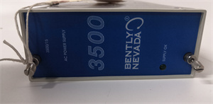
Excitation Voltage
|
12–30 VDC (current limited to 40 mA)
|
|
Operating Temperature
|
-40°C to +85°C (-40°F to 185°F)
|
|
Storage Temperature
|
-50°C to +85°C (-58°F to 185°F)
|
|
Humidity Tolerance
|
0%–95% non-condensing
|
|
Vibration Resistance
|
20g peak at 2kHz
|
|
Shock Resistance
|
30g peak
|
|
Contact Life
|
100,000 cycles at rated load
|
|
Termination Style
|
3-pin MIL-C-5015 connector (316L stainless steel)
|
|
Certifications
|
CE, UL, CSA, ATEX/IECEx (hazardous locations)
|
Customer Value & Operational Benefits
Enhanced Machinery Protection
The 177230-01-02-05’s high-precision vibration measurements enable early detection of incipient faults (e.g., bearing wear, rotor imbalance). By providing accurate, real-time data, it helps prevent catastrophic failures (e.g., turbine blade damage, pump seizure) and reduces unplanned downtime.
Seamless Integration with Control Systems
The 4–20 mA current loop output is compatible with almost any DCS/SCADA system, reducing the need for custom signal converters. For example, a power plant can connect the transmitter to a Siemens S7-1500 PLC to monitor turbine vibration, triggering an alarm if the signal exceeds the trip threshold.
Reduced Maintenance Costs
The hot-swappable design allows technicians to replace a faulty transmitter in minutes without interrupting the system. This minimizes labor costs and production losses—critical for facilities with tight maintenance budgets.
Compliance with Industry Standards
The transmitter’s certifications (CSA/ATEX/IECEx) ensure it meets the rigorous requirements of industries like oil & gas, power generation, and chemical processing. This compliance is essential for facilities seeking to adhere to regulatory or corporate safety standards.
Field Engineer’s Notes (From the Trenches)
When installing the 177230-01-02-05, always verify the sensor compatibility—the transmitter supports most industrial vibration sensors, but not all. Refer to the 177230 Series Compatibility Matrix to ensure the sensor is supported. I once saw a site where a contractor used a non-compatible sensor, resulting in no signal and a missed fault (bearing wear).Another gotcha: check the wiring polarity—the 4–20 mA signal is sensitive to reverse polarity. Use a multimeter to test the wiring before powering up the transmitter. I’ve fixed countless “no signal” faults by swapping the positive and negative wires.If the transmitter’s output is unstable, check the power supply—the excitation voltage must be between 12–30 VDC. I once traced a “noisy” signal to a faulty power supply, which was outputting 15 VDC instead of 24 VDC.Bently 3500/60 163179-01
Real-World Applications
-
Power Generation: Steam Turbine MonitoringA coal-fired power plant uses the 177230-01-02-05 to monitor a steam turbine’s bearing vibration. The transmitter receives signals from an accelerometer installed on the turbine’s bearing housing and transmits a 4–20 mA signal to the plant’s DCS. If the vibration exceeds 12 mils, the DCS triggers an alarm, allowing operators to shut down the turbine before damage occurs.
-
Oil & Gas: Centrifugal Compressor ProtectionAn offshore oil platform uses the 177230-01-02-05 to monitor a centrifugal compressor’s motor vibration. The transmitter is connected to a proximity probe installed on the motor’s shaft, providing real-time data to the platform’s PLC. If the vibration exceeds the trip threshold, the PLC shuts down the compressor, preventing impeller damage.
High-Frequency Troubleshooting FAQ
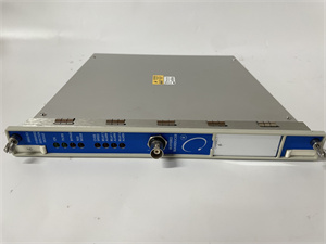
Q: What does the “FAULT” LED indicate on the 177230-01-02-05?
A: The red “FAULT” LED indicates a critical error, such as:
-
Sensor failure (e.g., broken wire, faulty probe).
-
Input signal out of range (e.g., too high or too low voltage).
-
Module hardware failure (e.g., corrupted firmware, damaged components).Check the transmitter’s manual for detailed fault codes and follow the manufacturer’s troubleshooting steps.
Q: Can the 177230-01-02-05 be used with non-Bently sensors?
A: No, the transmitter is designed exclusively for Bently Nevada sensors. Non-Bently sensors may not produce the correct signal characteristics, leading to inaccurate measurements.
Q: How do I calibrate the 177230-01-02-05?
A: The transmitter does not require regular calibration if the sensors are properly installed and maintained. However, if you suspect a calibration issue, use a vibration calibrator (e.g., Bently’s 177230 Calibrator) to test the transmitter’s input and output signals. Follow the manufacturer’s instructions for calibrator setup and testing.
Q: Why is the 177230-01-02-05 not transmitting data to the DCS?
A: Check three things first:
-
Power Supply: Ensure the excitation voltage is between 12–30 VDC.
-
Wiring: Check the 4–20 mA wiring for loose connections or incorrect polarity.
-
DCS Configuration: Verify that the DCS is configured for the correct signal type (4–20 mA) and range.
Commercial Availability & Pricing
Please note: The listed price is not the actual final price. It is for reference only and is subject to appropriate negotiation based on current market conditions, quantity, and availability.