
Description
System Architecture & Operational Principle
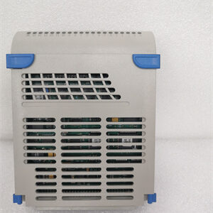
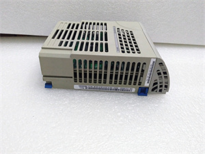
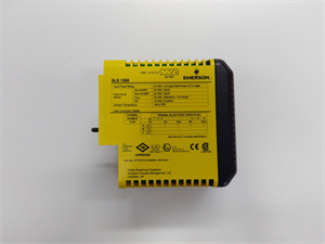
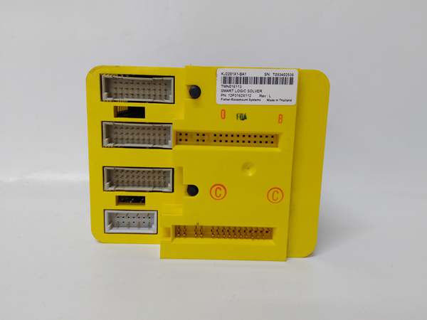
The Emerson KJ2201X1-BA1 is a Smart Logic Solver (SLS) residing at Level 2 (Control) of the Purdue Model. It sits in a DeltaV SIS rack, receiving safety trip commands from process sensors (e.g., pressure, temperature) via redundant I/O modules. The solver executes pre-programmed safety logic (e.g., 2oo3 voting) and outputs digital signals to final control elements (e.g., solenoids, motor brakes) to bring a process to a safe state. Its key advantage is the TMR backplane, which allows three independent processors to run identical logic and vote on outputs, masking a single processor failure. The backplane also provides galvanic isolation between the three channels, preventing common-mode failures.
Core Technical Specifications
-
Processor Architecture: Triple Modular Redundant (TMR) 32-bit
-
Safety Integrity Level: SIL 3 (IEC 61508/61511)
-
Scan Cycle Time: <10 ms
-
Power Supply: 24 VDC (±10%), 1.5 A per channel
-
Communication: SISnet (redundant), Modbus TCP/IP
-
I/O Capacity: Up to 256 I/O points via expansion carriers
-
Operating Temperature: -40°C to +70°C
-
Storage Temperature: -40°C to +85°C
-
Humidity Tolerance: 5% to 95% non-condensing
-
Dimensions (W×H×D): 25.4 cm × 4.4 cm × 17.8 cm (10 in × 1.75 in × 7 in)
-
Weight: 1.8 kg (4 lbs)

Emerson KJ2201X1-BA1
Customer Value & Operational Benefits
Preventing Unplanned Outages
The TMR design means a single processor or I/O card failure won’t trigger a spurious trip, but the system remains in a fail-safe state. This directly cuts downtime from nuisance shutdowns.
Fast Root-Cause Analysis
The controller’s diagnostic buffer logs event timestamps with millisecond resolution. When a fault occurs, you can trace the sequence of events across all three channels to pinpoint the initiating cause, slashing mean-time-to-repair (MTTR).
Simplified Validation
Emerson provides a pre-built library of function blocks for common SIFs (e.g., ESD, F&G). This reduces the amount of custom code you need to validate, cutting project time and cost.
Field Engineer’s Notes (From the Trenches)
When commissioning a KJ2201X1-BA1, always check the backplane power jumpers first. I’ve seen a unit go into cold standby because a jumper was missing on one of the three power segments. The module gets power, the OK light is on, but it won’t execute logic. A simple visual check of the jumpers against the wiring diagram saves a 4-hour callout. Also, use shielded twisted pair for the SISnet connections and terminate the ends properly. A bad termination causes intermittent comms that look like a processor fault.
Real-World Applications
-
Offshore Oil Platform Emergency Shutdown (ESD)The KJ2201X1-BA1 receives signals from high-high pressure transmitters on a wellhead. If two out of three transmitters agree the pressure is too high, the solver sends a trip signal to the wellhead master valve, closing it in under 100 ms.
-
Chemical Reactor InterlockIn a hydrocracker, the solver monitors reactor temperature and feed flow. If temperature exceeds a setpoint while flow is low (risk of runaway reaction), it trips the feed pump and opens the quench valve simultaneously.
Emerson KJ2201X1-BA1
High-Frequency Troubleshooting FAQ
Q: What does a flashing red FAULT LED indicate on the KJ2201X1-BA1?
A: It signals a mismatch between the three processor channels. Check the diagnostic log via DeltaV Explorer. Common causes are a corrupt program load, a failing I/O card in one channel, or a backplane power issue on one segment. Resolving requires comparing the logs from each channel to find the divergent point.
Q: Can the KJ2201X1-BA1 be replaced with a standard DeltaV controller?
A: No. The KJ2201X1-BA1 has TMR architecture and SIL 3 certification, which standard controllers lack. Using a non-SIS controller in a safety loop invalidates the safety case and insurance. For migration, you must replace it with another SIL 3 certified logic solver, like the newer KJ3243X1-BA1.
Q: How do I verify the TMR voting is working correctly?
A: Force a discrepancy in one channel (e.g., force a digital input ON in channel A only). The output LEDs should show the majority state (OFF if B and C are OFF). The diagnostic log will flag the discrepancy. If the output follows the forced input, the voting logic is compromised and the unit is unsafe for operation.
Commercial Availability & Pricing
Please note: The listed price is not the actual final price. It is for reference only and is subject to appropriate negotiation based on current market conditions, quantity, and availability.