Description
System Architecture & Operational Principle
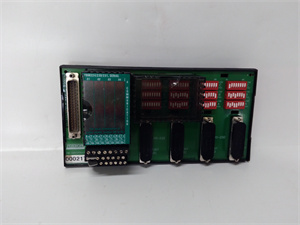
The Foxboro FBM218 is an 8-channel redundant HART communication output module within the Foxboro I/A Series DCS, designed for Level 1 (Device) or Level 2 (Control) of the Purdue Model in industrial automation. It resides in the I/A Series FBM rack (typically in field I/O cabinets) and serves as the bridge between I/A Series controllers (e.g., CP4000 control processors) and smart field devices (e.g., HART-enabled valve positioners, actuators).
Upstream Communication
Receives digital control signals (e.g., “set valve position to 50%”) from I/A Series controllers via the FBM rack’s backplane. These signals represent process control commands (e.g., flow rate, pressure setpoints) generated by the DCS.
Downstream Communication
Converts the digital signals into 4-20 mA analog signals (superimposed with HART digital communication) for each of the 8 output channels. The HART protocol enables bidirectional communication with smart field devices, allowing the DCS to:
-
Send configuration commands (e.g., “calibrate valve positioner”);
-
Receive diagnostic data (e.g., “valve stem position,” “device health status”);
-
Adjust control parameters (e.g., “change gain”) without interrupting the analog signal.
The module uses channel-to-channel isolation (1500 V RMS) to prevent electrical interference between channels, ensuring accurate signal transmission even in noisy industrial environments.
Operational Advantages
-
Redundant Architecture: Paired modules (Master-Tracker) ensure continuous operation—if the Master fails, the Tracker takes over within milliseconds, preventing process interruptions.
-
HART Integration: Combines analog control with digital diagnostics, reducing the need for manual field visits and enabling predictive maintenance.
-
High Precision: 16-bit D/A conversion and ±0.1% accuracy ensure precise control of field devices, critical for maintaining process stability.
-
Hot-Swappable Design: Can be replaced without shutting down the I/A Series system, minimizing production losses during maintenance.
Core Technical Specifications
|
Attribute
|
Specification
|
|---|---|
|
Channel Count
|
8 independent, isolated analog output channels
|
|
Output Signal Type
|
4-20 mA current loop (superimposed with HART digital signal)
|
|
Accuracy
|
±0.1% of full scale (typical)
|
|
Resolution
|
16-bit D/A conversion
|
|
Power Supply
|
24 VDC (±10%, 5W max)
|
|
Operating Temperature
|
-40°C to +70°C (-40°F to 158°F)
|
|
Storage Temperature
|
-40°C to +85°C (-40°F to 185°F)
|
|
Humidity Tolerance
|
5%–95% non-condensing
|
|
Isolation
|
1500 V RMS channel-to-channel; 1500 V RMS channel-to-bus
|
|
HART Throughput
|
Up to 2 digital messages per second per device
|
|
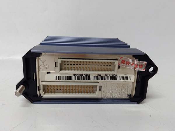
Dimensions (W×H×D)
|
~130 mm × 200 mm × 30 mm (5.12 in × 7.87 in × 1.18 in)
|
|
Weight
|
~0.5 kg (1.1 lbs)
|
|
Certifications
|
CE, UL, CSA, ATEX, IECEx
|
|
Compatibility
|
Foxboro I/A Series DCS; works with CP4000 control processors
|
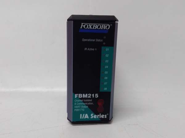
FOXBORO FBM215
Customer Value & Operational Benefits
Enhanced Process Reliability
The FBM218’s redundant architecture and high isolation ensure accurate control of field devices, reducing false alarms and ensuring reliable process control. For example, a chemical plant using the module to control reactor feed valves can maintain a consistent feed rate, reducing waste and improving yield.
Reduced Downtime with Redundancy
The Master-Tracker configuration minimizes unplanned downtime—if one module fails, the other takes over seamlessly. This is critical for 24/7 operations like oil & gas production, where even a short outage can result in significant costs.
Cost-Effective I/O Expansion
The 8-channel design reduces the number of modules needed for complex control tasks, saving cabinet space and installation costs. Additionally, the module’s compatibility with I/A Series systems eliminates the need for custom wiring or protocol converters.
Compliance with Industry Standards
The module’s certifications (CE, UL, ATEX) ensure it meets the rigorous requirements of industries like oil & gas, power generation, and chemical processing. This compliance is essential for facilities seeking to adhere to regulatory or corporate safety standards.
Field Engineer’s Notes (From the Trenches)
When installing the FBM218, always use shielded twisted-pair cables for field wiring—unshielded cables can pick up electromagnetic interference (EMI) from nearby power lines, leading to inaccurate signal readings. I once saw a site where a contractor used unshielded cables, resulting in a 5% error in valve position control. Shielded cables eliminated the problem immediately.Another gotcha: verify the HART device address—each HART-enabled field device must have a unique address (1–15) to communicate with the module. If two devices have the same address, the module will not be able to distinguish between them, leading to communication errors. Use a HART communicator to check and set the addresses before connecting the devices.If the module’s “FAULT” LED is red, check the field wiring first—loose or reversed wires are a common cause of faults. Use a multimeter to test for continuity between the field device and the module’s output terminals. Also, ensure the module’s shield is grounded to the I/A Series rack’s earth ground to reduce EMI.
Real-World Applications
-
Oil & Gas: Offshore Platform Valve ControlAn offshore oil platform uses the FBM218 to control 8 HART-enabled valve positioners on a crude oil pipeline. The module sends 4-20 mA signals to the positioners, adjusting their opening to maintain a consistent flow rate. HART diagnostics allow technicians to monitor valve health remotely, reducing the need for offshore visits.
-
Chemical Processing: Reactor Temperature ControlA chemical plant uses the FBM218 to control 8 HART-enabled actuators on a polymerization reactor. The module adjusts the actuators’ position to maintain the reactor temperature within the optimal range (e.g., 80°C). HART communication enables the DCS to receive real-time temperature data from the reactor, improving process stability.

FOXBORO FBM215
High-Frequency Troubleshooting FAQ
Q: What does the “FAULT” LED indicate on the FBM218?
A: The red “FAULT” LED indicates a critical error, such as:
-
Field Wiring Issue: Loose or reversed wires between the module and the field device.
-
HART Communication Error: Duplicate HART addresses or faulty HART devices.
-
Module Hardware Failure: Corrupted firmware or damaged components.Check the I/A Series diagnostic software for detailed fault codes and follow the manufacturer’s troubleshooting steps.
Q: Can the FBM218 be used with non-HART devices?
A: Yes, the module supports both HART-enabled and non-HART 4-20 mA devices. However, non-HART devices will not benefit from the HART protocol’s diagnostic features.
Q: How do I replace the FBM218?
A: Follow these steps:
-
Power Down: Turn off the I/A Series rack’s main power supply.
-
Remove Old Module: Unscrew the module from the I/A Series carrier (use a Phillips screwdriver).
-
Install New Module: Secure the new FBM218 to the carrier and tighten the screws.
-
Power Up: Turn on the main power supply and verify the module’s operation (check the “OK” LED).
Q: Why is the FBM218 not sending signals to field devices?
A: Check three things first:
-
Field Device Power: Ensure the field device (e.g., valve positioner) is powered (use a multimeter to measure the voltage).
-
Wiring: Check the shielded twisted-pair cable for loose connections or damage.
-
Module Configuration: Use the I/A Series configuration software to verify that the module is configured for the correct output type (4-20 mA).
Commercial Availability & Pricing
Please note: The listed price is not the actual final price. It is for reference only and is subject to appropriate negotiation based on current market conditions, quantity, and availability.