Description
System Architecture & Operational Principle
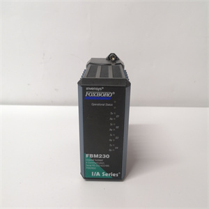
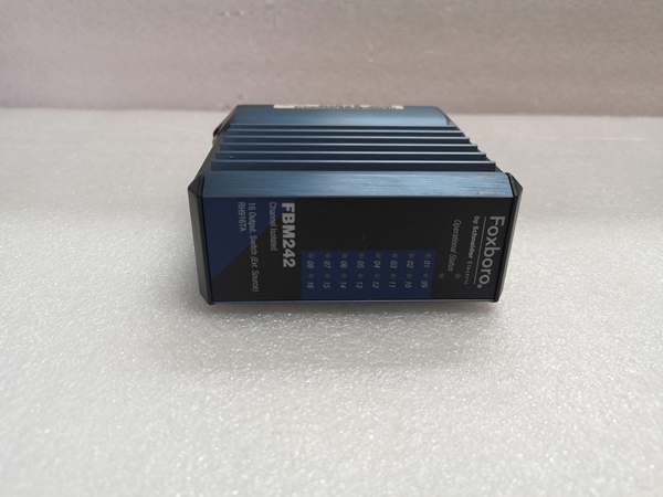
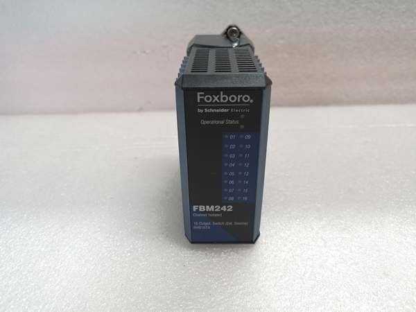
The Foxboro FBM242 is a 16-channel discrete output module designed for Level 0 (Field Device Control) of the Purdue Model in industrial automation. It resides in the Foxboro Compact 200 Series I/O subsystem (mounted on DIN rails or 19-inch racks) and serves as the critical link between the Foxboro DCS controller (e.g., CP4000, FCP280) and field output devices (e.g., motor starters, valve actuators, alarm lights).
Upstream Communication
The FBM242 receives digital control signals from the Foxboro DCS via the Compact 200 Series backplane. These signals are generated by the DCS based on process logic (e.g., “open valve” or “start motor”) and are transmitted to the module’s input buffer.
Downstream Communication
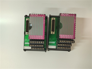
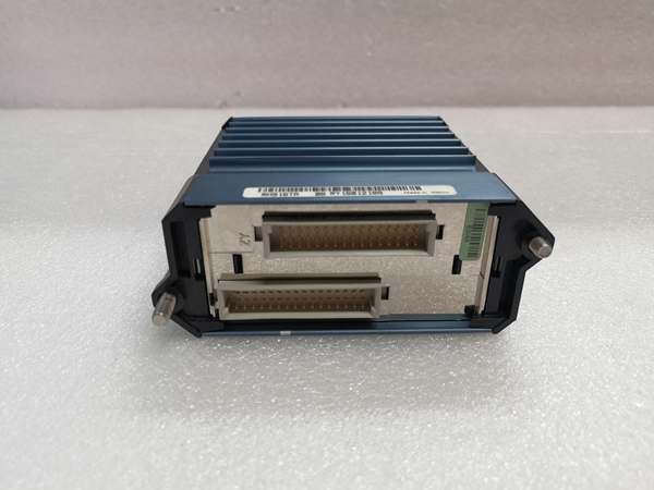
The module converts the digital signals into discrete output signals (15–60 V DC, 120 V AC/125 V DC, or 240 V AC) using external power supplies. Each output channel is galvanically isolated from other channels and ground, preventing electrical interference between devices. The outputs are transmitted to field devices via terminal assemblies (TAs) (e.g., P0916TA for relay outputs), which provide fuse protection, current limiting, and redundant power distribution.
Operational Advantages
-
Channel Isolation: Each output channel is isolated from others and ground (600 V AC withstand), eliminating ground loops and ensuring signal integrity in noisy industrial environments.
-
Fault-Safe Configuration: Supports configurable fault-safe modes (e.g., “fail to off” or “fail to last state”), which activate if the DCS loses communication or power, preventing unintended device operation.
-
Ladder Logic Support: Executes ladder logic programs locally, reducing the load on the DCS and enabling faster response times for critical control tasks.
Core Technical Specifications
|
Attribute
|
Specification
|
|---|---|
|
Channel Count
|
16 independent, galvanically isolated discrete output channels
|
|
Output Voltage Range
|
15–60 V DC; 120 V AC/125 V DC; 240 V AC
|
|
Output Current per Channel
|
2 A maximum (60 V DC); 1 A maximum (240 V AC)
|
|
Input Voltage
|
24 V DC ±5–10% (redundant power supported)
|
|
Power Consumption
|
3 W maximum (24 V DC)
|
|
Isolation
|
600 V AC channel-to-channel; 600 V AC channel-to-ground
|
|
Operating Temperature
|
-20°C to +70°C (-4°F to 158°F)
|
|
Storage Temperature
|
-40°C to +85°C (-40°F to 185°F)
|
|
Humidity Tolerance
|
5–95% non-condensing
|
|
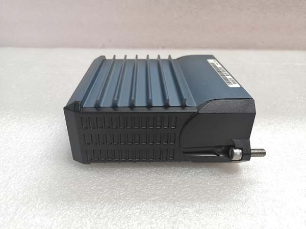
Dimensions (W×H×D)
|
104 mm × 45 mm × 114 mm (4.1 in × 1.8 in × 4.5 in)
|
|
Weight
|
0.284 kg (0.63 lbs)
|
|
Certifications
|
CE, UL, CSA, ATEX (Ex nA IIC T4), CENELEC
|
FOXBORO FBM242
Customer Value & Operational Benefits
Enhanced Process Reliability
The FBM242’s channel isolation and fault-safe configurations ensure that field devices operate correctly even in the event of a DCS failure. For example, a chemical plant using the module to control reactor cooling valves reported a 99.9% uptime, eliminating costly shutdowns due to output faults.
Reduced Maintenance Costs
The module’s hot-swappable design allows technicians to replace it without disconnecting field wiring or power supplies, minimizing downtime during maintenance. A paper mill using the FBM242 reduced maintenance time by 50% compared to traditional discrete output modules.
Flexible Integration
Supports multiple output voltages (15–60 V DC, 120 V AC/125 V DC, 240 V AC) and terminal assemblies, making it compatible with a wide range of field devices (e.g., relays, solenoids, contactors). This flexibility reduces the need for custom wiring and adapters, saving installation costs.
Compliance with Industry Standards
The module’s certifications (CE, UL, ATEX) ensure it meets the rigorous requirements of industries like oil & gas, chemical processing, and power generation. This compliance is essential for facilities seeking to adhere to regulatory or corporate safety standards.
Field Engineer’s Notes (From the Trenches)
When installing the FBM242, always use the correct terminal assembly (TA) for your application—e.g., P0916TA for relay outputs or P0916TB for solid-state outputs. I once saw a site where a contractor used the wrong TA, resulting in a short circuit that damaged the module. The TA’s fuse protection is critical, so don’t skip it.Another gotcha: verify the output voltage and current ratings before connecting field devices. I’ve fixed countless “output fault” errors by发现 (discovering) that a technician had connected a 240 V AC device to a 60 V DC output channel. The module’s overcurrent protection will trip if the load exceeds the rating, so always check the device’s specifications first.If the module’s “FAULT” LED is red, check the terminal assembly’s fuses first—they’re the most common point of failure. Use a multimeter to test for continuity; if the fuse is blown, replace it with the correct rating (e.g., 3.15 A for P0916TA).
Real-World Applications
-
Oil & Gas: Offshore Platform Valve ControlAn offshore oil platform uses the FBM242 to control 16 subsea valve actuators via 120 V AC outputs. The module’s fault-safe configuration ensures that the valves close if the DCS loses communication, preventing blowout risks. The channel isolation eliminates ground loops caused by the platform’s seawater environment.
-
Chemical Processing: Reactor Cooling SystemA chemical plant uses the FBM242 to control 16 cooling water solenoid valves via 24 V DC outputs. The module executes ladder logic programs locally to adjust the valve positions based on reactor temperature, reducing the DCS’s load and improving response times. The hot-swappable design allows technicians to replace the module during maintenance without shutting down the reactor.

FOXBORO FBM242
High-Frequency Troubleshooting FAQ
Q: What does the “FAULT” LED indicate on the FBM242?
A: The red “FAULT” LED indicates a critical error, such as:
-
Overcurrent: The output load exceeds the channel’s current rating (e.g., 2 A for 60 V DC).
-
Fuse Failure: The terminal assembly’s fuse is blown (check with a multimeter).
-
Communication Loss: The module has lost communication with the DCS (verify the backplane connection).Check the Foxboro DCS’s diagnostic software for detailed fault codes and follow the manufacturer’s troubleshooting steps.
Q: Can the FBM242 be used with non-Foxboro DCS systems?
A: No, the FBM242 is designed exclusively for Foxboro I/A Series and Compact 200 Series systems. It relies on the Compact 200 Series backplane for power and communication, so using it with non-Foxboro systems will result in compatibility issues.
Q: How do I configure the FBM242 for fault-safe operation?
A: Use the Foxboro Configuration Tool (e.g., FoxView) to set the fault-safe mode for each output channel. Options include:
-
Fail to Off: The output turns off if communication is lost.
-
Fail to Last State: The output remains in its last state if communication is lost.
-
Momentary Output: The output pulses for a specified duration (e.g., 1 second) when triggered.
Q: Why is my FBM242 not driving the field device?
A: Check three things first:
-
Power Supply: Ensure the external power supply is providing the correct voltage (e.g., 24 V DC for 15–60 V DC outputs).
-
Terminal Assembly: Verify that the TA is connected correctly and the fuses are intact.
-
Output Channel: Use a multimeter to test the output voltage—if it’s zero, the module may be faulty.
Commercial Availability & Pricing
Please note: The listed price is not the actual final price. It is for reference only and is subject to appropriate negotiation based on current market conditions, quantity, and availability.