Description
System Architecture & Operational Principle
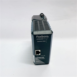
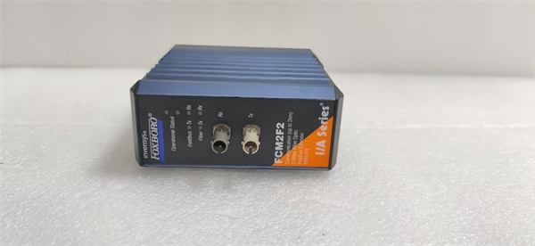
The Foxboro FCM2F2 is a fiber optic fieldbus extender within the Foxboro I/A Series DCS, designed to extend the reach of 200 Series Fieldbus Modules (FBMs) over long distances using fiber optic cables. It resides in standard I/A Series baseplates (alongside FBMs) and serves as the bridge between FBMs (field-mounted) and DCS controllers (e.g., CP60, FCP270).
Upstream Communication
Receives 2 Mbps fieldbus signals from FBMs via the baseplate’s backplane. These signals represent process data (e.g., pressure, temperature) from field devices (e.g., transmitters, valves).
Downstream Communication
Converts the electrical fieldbus signals to optical signals and transmits them over multimode fiber optic cables to other FCMs or DCS controllers. The module supports point-to-point or multi-drop configurations, with a maximum transmission distance of 2 km (1.24 miles) per segment.
Operational Advantages
-
Noise Immunity: Fiber optic cables are unaffected by electromagnetic interference (EMI), radio frequency interference (RFI), or lightning, making them ideal for harsh industrial environments (e.g., near rotating machinery, high-voltage lines).
-
Long Distance: Extends FBM communication up to 2 km, eliminating the need for long copper cable runs and reducing installation costs.
-
Redundancy: Can be paired with another FCM2F2 for redundant communication, ensuring uninterrupted operation if one module fails.
-
Hot-Swappable: Can be replaced without shutting down the DCS, minimizing downtime during maintenance.
Core Technical Specifications
|
Attribute
|
Specification
|
|---|---|
|
Module Type
|
2 Mbps Fiber Optic Fieldbus Extender
|
|
Model Variants
|
FCM2F2 (RH914YZ), FCM2F4 (RH917JA), FCM2F10 (RH916TQ)
|
|
Fiber Type
|
Multimode (62.5 µm core, 125 µm cladding)
|
|
Max Transmission Distance
|
2 km (1.24 miles) per segment
|
|
Data Rate
|
2 Mbps
|
|
Connector Type
|
ST-type (for fiber optic cables)
|
|
Operating Temperature
|
-20°C to +70°C (-4°F to 158°F)
|
|
Storage Temperature
|
-40°C to +85°C (-40°F to 185°F)
|
|
Humidity Tolerance
|
5–95% non-condensing
|
|
Power Supply
|
Supplied via baseplate (24 V DC ±10%)
|
|
Power Consumption
|
≤ 5 W
|
|
Dimensions (W×H×D)
|
~100 mm × 30 mm × 150 mm (3.94 in × 1.18 in × 5.91 in) (estimated)
|
|
Weight
|
~0.5 kg (1.1 lbs)
|
|
Certifications
|
CE, UL, CSA, ATEX (Ex nA IIC T4)
|
FOXBORO FCM2F2
Customer Value & Operational Benefits
Reduced Installation Costs
By allowing FBMs to be installed near field devices (instead of in a central control room), the FCM2F2 eliminates the need for long copper cable runs. For example, a chemical plant reduced cable costs by 40% by using FCM2F2 to extend FBM communication to remote reactors.
Improved Signal Integrity
Fiber optic cables are immune to EMI/RFI, which is critical in environments with rotating machinery (e.g., turbines) or high-voltage equipment (e.g., transformers). A paper mill reported a 90% reduction in communication errors after replacing copper cables with fiber optic cables and FCM2F2 extenders.
Increased Reliability
The redundant configuration (pairing two FCM2F2 modules) ensures uninterrupted communication if one module fails. For an oil refinery, this meant avoiding a potential shutdown worth $100,000 per hour.
Simplified Maintenance
The hot-swappable design allows technicians to replace a faulty FCM2F2 without shutting down the DCS. A power plant reduced maintenance downtime by 50% using this feature.
Field Engineer’s Notes (From the Trenches)
When installing the FCM2F2, always use multimode fiber optic cables with ST-type connectors—single-mode cables are not compatible and will cause signal loss. I once saw a site where a contractor used single-mode cables, resulting in a “no signal” fault. Switching to multimode cables fixed the issue immediately.Another gotcha: verify the fiber optic cable’s attenuation—use a OTDR (Optical Time-Domain Reflectometer) to check for signal loss. If the attenuation exceeds 1 dB/km at 1300 nm, the cable is too old or damaged and needs to be replaced.If the FCM2F2’s “LINK” LED is off, check the fiber optic connectors—dust or dirt on the connectors can block the signal. Use a lint-free cloth and isopropyl alcohol to clean the connectors before reconnecting.
Real-World Applications
-
Oil & Gas: Offshore Platform Remote MonitoringAn offshore oil platform uses FCM2F2 extenders to connect FBMs (monitoring subsea wells) to the central DCS. The 2 km fiber optic cables allow the FBMs to be installed on the platform’s deck, reducing the need for long underwater cables.
-
Chemical Processing: Reactor Temperature ControlA chemical plant uses FCM2F2 extenders to connect FBMs (monitoring reactor temperature) to the DCS. The fiber optic cables are routed through a high-voltage cable tray, avoiding EMI from nearby transformers.
-
Power Generation: Turbine Vibration MonitoringA power plant uses FCM2F2 extenders to connect FBMs (monitoring turbine vibration) to the DCS. The fiber optic cables are immune to EMI from the turbine’s rotating machinery, ensuring accurate vibration data.

FOXBORO FCM2F2
High-Frequency Troubleshooting FAQ
Q: What does a “no link” fault indicate on the FCM2F2?
A: A “no link” fault usually means:
-
Fiber Optic Cable Issue: The cable is broken, disconnected, or has the wrong connector (e.g., single-mode instead of multimode).
-
Connector Contamination: Dust or dirt on the ST-type connectors is blocking the signal.
-
Module Failure: The FCM2F2’s optical transmitter/receiver is faulty.Use an OTDR to test the cable and a multimeter to check the module’s power supply.
Q: Can the FCM2F2 be used with single-mode fiber optic cables?
A: No, the FCM2F2 is designed for multimode fiber optic cables (62.5 µm core). Single-mode cables will cause signal loss and are not compatible.
Q: How do I configure the FCM2F2 for redundant operation?
A: Pair two FCM2F2 modules on adjacent baseplates. Connect the fiber optic cables from each FCM to the other baseplate’s FCM. The DCS will automatically switch to the redundant FCM if one fails.
Q: Why is the FCM2F2’s “LINK” LED blinking?
A: A blinking “LINK” LED indicates signal degradation (e.g., high attenuation in the fiber optic cable). Check the cable’s attenuation with an OTDR and replace it if necessary.
Commercial Availability & Pricing
Please note: The listed price is not the actual final price. It is for reference only and is subject to appropriate negotiation based on current market conditions, quantity, and availability.