
Description
System Architecture & Operational Principle
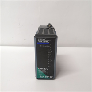
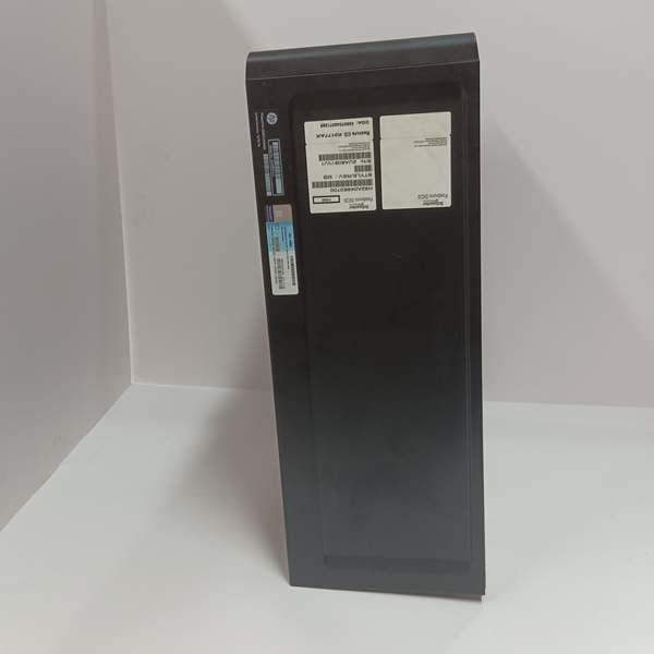
The H92904CC0500 is a 4-channel analog input (AI) module designed for the Foxboro I/A Series DCS, typically installed in I/O racks (Purdue Level 1) that connect to field instruments (transmitters, sensors) and feed data to control processors at Level 2. Each channel accepts a single-ended 4–20 mA current loop, which is converted to a 16-bit digital value for use in control logic, alarming, and historical trending.
The module contains per-channel signal conditioning (precision resistor networks, filtering) and 1500 VDC optical isolation to break ground loops and protect the DCS from high-voltage transients or field-side faults. The 4–20 mA range is standardized for process instrumentation, with 4 mA representing the lower range value (LRV) and 20 mA the upper range value (URV).
Internally, the H92904CC0500 uses a sigma-delta ADC architecture for high-resolution conversion, with a typical update rate of 10–20 ms per channel. The digitized values are transmitted to the I/A Series control processor via the rack’s backplane data bus. The module is hot-swappable when installed in a supported I/A Series rack, allowing replacement without shutting down the entire system—a critical feature for high-availability process units.
Core Technical Specifications
-
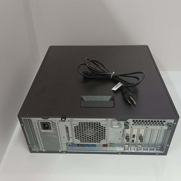
Physical Interface: 4x 2-terminal screw-clamp connectors (one per channel) for 4–20 mA loops
-
Input Range: 4–20 mA (selectable 0–20 mA via jumper)
-
Resolution: 16 bits (65,536 counts)
-
Accuracy: ±0.05% of span (at 25°C)
-
Isolation: 1500 VDC channel-to-channel, 500 VDC channel-to-ground
-
Input Impedance: 250 Ω nominal (converts 4–20 mA to 1–5 VDC internally)
-
Update Rate: 10–20 ms per channel (software-configurable)
-
Operating Temperature: -40°C to +70°C (-40°F to +158°F)
-
Storage Temperature: -55°C to +85°C (-67°F to +185°F)
-
Humidity: 5–95% RH non-condensing
-
Common Mode Rejection Ratio (CMRR): >120 dB at 50/60 Hz
-
Dimensions: ~30 mm × 128 mm × 145 mm (1.2 in × 5.0 in × 5.7 in) per module
-
Weight: ~0.5 kg (1.1 lbs) per module
-
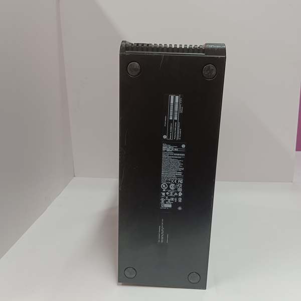
Certifications: UL/cUL, CE, ATEX/IECEx (hazardous area approvals with appropriate barriers)
Customer Value & Operational Benefits
High-Resolution Signal Conversion for Precise Process Control
The 16-bit resolution and ±0.05% accuracy ensure that small changes in process variables (e.g., pressure, flow) are detected and reported accurately. This is essential for tighter control loops in applications like reactor temperature regulation or gas chromatograph sampling, where even minor deviations can impact product quality.
Robust Isolation Prevents Ground Loops and Transient Damage
Channel-to-channel and channel-to-ground isolation eliminates interference from field-side ground potential differences, which are common in large plants with multiple grounding zones. This protects the DCS from voltage spikes caused by lightning, motor startups, or faulty transmitters, reducing unplanned downtime.
Hot-Swappable Design Minimizes Maintenance Impact
The ability to replace a faulty H92904CC0500 module without powering down the rack is invaluable for continuous process industries (chemicals, pharmaceuticals, oil & gas). Maintenance can be performed during scheduled plant rounds, avoiding costly shutdowns or production losses.
Field Engineer’s Notes (From the Trenches)
When wiring 4–20 mA loops to the H92904CC0500, always use shielded twisted pair cable and terminate the shield at the module end only—grounding both ends creates ground loops that manifest as erratic readings or drift. I once spent hours troubleshooting a pressure transmitter that seemed to “drift” until I realized the shield was bonded to the transmitter housing and the module chassis. Also, verify the loop resistance doesn’t exceed 600 Ω (including cable resistance)—higher resistance drops voltage below the module’s 1 VDC minimum input, causing a 0 mA reading.
Real-World Applications
In a Texas petrochemical refinery, the H92904CC0500 monitors four pressure transmitters on a catalytic reformer’s feed line. The 16-bit resolution allows the DCS to detect pressure fluctuations as small as 0.01 psi, triggering early warnings for catalyst bed plugging. The 1500 VDC isolation prevents interference from nearby high-voltage motors, ensuring reliable data for the advanced process control (APC) system.
On an offshore oil platform, the H92904CC0500 is used in the wellhead control module to read 4–20 mA signals from subsea flowmeters. The module’s wide operating temperature range (-40°C to +70°C) withstands the platform’s unheated control room, while ATEX certification (with intrinsic safety barriers) ensures safe operation in potentially explosive atmospheres. Hot-swapping failed modules during crew rotations minimizes impact on production.