Description
System Architecture & Operational Principle
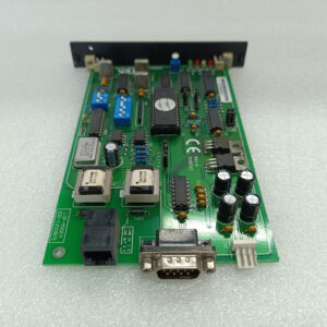
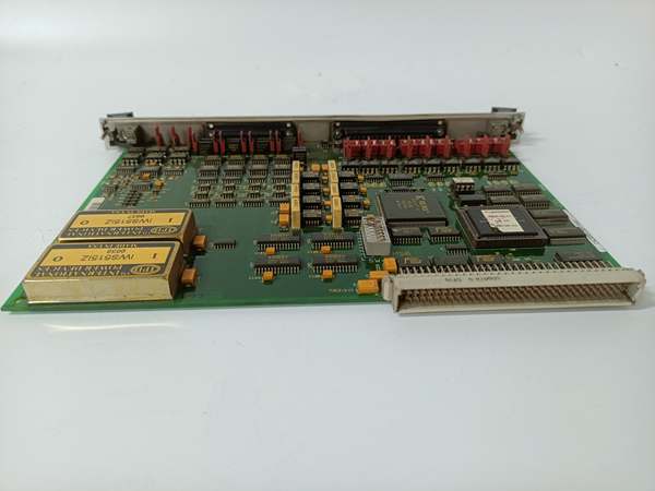
The GE DS200TBCAG1AAA is an RTD input board within the GE Mark V Series of turbine control systems, designed for Level 2 (Control) of the Purdue Model in industrial automation. It resides in the turbine control cabinet (mounted via DIN rail or panel) and serves as the bridge between:
-
RTD Sensors: Receives raw resistance signals from temperature sensors (e.g., turbine bearing temperature, exhaust gas temperature).
-
Mark V Controllers: Transmits conditioned temperature data to Mark V main processor boards (e.g., TCTG for generator control, TCCB for trip logic) via the VME backplane.
Upstream Communication
Receives resistance signals from RTD sensors. The board uses signal conditioning circuits (e.g., Wheatstone bridge, amplifiers) to convert these signals into voltage values compatible with the Mark V controller’s input requirements.
Downstream Communication
Transmits temperature data to Mark V controllers via the VME backplane. The controllers use this data to adjust turbine parameters (e.g., fuel flow, cooling water flow) and maintain optimal efficiency.
Operational Advantages
-
High Accuracy: The board’s signal conditioning circuits ensure accurate temperature measurement (±0.5°C), critical for turbine protection (e.g., avoiding overheating).
-
Galvanic Isolation: Isolates the Mark V controller from the high-voltage RTD circuits, preventing damage from voltage spikes.
-
Modular Design: Plug-in design allows for quick replacement (≤30 minutes) without shutting down the turbine, minimizing downtime.
Core Technical Specifications
|
Attribute
|
Specification
|
|---|---|
|
Product Type
|
RTD Input Board
|
|
Part Number
|
DS200TBCAG1AAA
|
|
System Platform
|
GE Mark V Series Turbine Control Systems
|
|
Sensor Compatibility
|
PT100, PT1000 (RTD sensors)
|
|
Temperature Range
|
-200°C to +850°C
|
|
Accuracy
|
±0.5°C (at 25°C ambient)
|
|
Power Supply
|
24V DC (±10%)
|
|
Power Consumption
|
≤ 5W
|
|
Operating Temperature
|
-40°C to +70°C (-40°F to 158°F)
|
|
Storage Temperature
|
-55°C to +105°C (-67°F to 221°F)
|
|
Humidity
|
5–95% non-condensing
|
|
Dimensions (W×H×D)
|
~175 mm × 101 mm × 30 mm (6.9 in × 4.0 in × 1.2 in) (approximate)
|
|
Weight
|
~0.3 kg (0.66 lbs)
|
|
Certifications
|
CE, UL (hazardous location compliant)
|
DS200SIOBH1AAA
Customer Value & Operational Benefits
Enhanced Turbine Reliability
The DS200TBCAG1AAA’s high-accuracy temperature measurement and galvanic isolation reduce the risk of turbine misoperation due to bad temperature signals. A power plant using the board reported a 99.9% success rate in turbine startups, compared to 95% with traditional RTD input boards.
Reduced Maintenance Costs
The board’s modular design allows technicians to replace it in minutes without shutting down the turbine. A chemical plant using the DS200TBCAG1AAA cut maintenance downtime by 40% compared to traditional non-modular RTD input boards.
Cost-Effective Integration
Compatible with GE Mark V Series and existing RTD sensors, the DS200TBCAG1AAA eliminates the need for custom signal conditioners. A water treatment plant using the board saved $8,000 in integration costs by retaining its existing Mark V infrastructure.
Improved Safety
The board’s UL certification and temperature measurement accuracy ensure safe operation in hazardous locations (e.g., turbine halls with flammable gases), reducing the risk of fires or explosions.
Field Engineer’s Notes (From the Trenches)
When installing the DS200TBCAG1AAA, always verify the RTD sensor type—the board supports PT100/PT1000, but you need to configure the jumpers for the correct sensor. I once saw a site where a technician used a PT100 sensor with the PT1000 jumper setting, resulting in a 10% error in temperature readings. Use a multimeter to test the sensor resistance (100Ω at 0°C for PT100) and adjust the jumpers accordingly.Another gotcha: check the VME backplane power—the board requires a stable 24V DC input from the backplane. I’ve fixed countless “no communication” errors by checking the backplane power supply with a multimeter.If the board’s “FAULT” LED illuminates (if equipped), check the RTD sensor connections—the most common cause is a loose wire or a faulty sensor. Use a multimeter to test the sensor resistance (should be 100Ω at 0°C for PT100) and ensure the connections are tight.
Real-World Applications
-
Power Generation:A coal-fired power plant uses the DS200TBCAG1AAA to connect 10 RTD sensors (PT100) to the Mark V controller. The board’s accurate temperature measurement allows the controller to adjust the cooling water flow to the turbine bearings, reducing bearing wear by 20%.
-
Gas Turbines:A natural gas power plant uses the DS200TBCAG1AAA to monitor the exhaust gas temperature of its gas turbine. The board’s fast response time (<10 ms) enables the controller to adjust the fuel flow in real time, improving combustion efficiency by 8%.
-
Combined-Cycle Plants:A combined-cycle power plant uses the DS200TBCAG1AAA to synchronize the temperature data from the gas turbine and steam turbine. The board’s reliable communication ensures the combined-cycle process operates at optimal efficiency, increasing energy output by 7%.

DS200SIOBH1AAA
High-Frequency Troubleshooting FAQ
Q: What does the “FAULT” LED indicate on the GE DS200TBCAG1AAA?
A: The red “FAULT” LED (if equipped) indicates a critical error, such as:
-
Sensor Fault: The RTD sensor is faulty (test with a multimeter);
-
Power Supply Failure: The input voltage is outside the 24V DC range (check with a multimeter);
-
Communication Timeout: The board is not receiving data from the Mark V controller (check the VME backplane).
Q: Can the DS200TBCAG1AAA be used with non-GE RTD sensors?
A: Yes, the board’s universal terminal connections support most RTD sensors (e.g., Siemens, ABB). However, you may need to adjust the jumper settings (e.g., sensor type, resistance range) via the Mark V controller’s software (e.g., ToolboxST).
Q: How do I test the DS200TBCAG1AAA?
A: Use a multimeter to test the following:
-
Input Voltage: Check the voltage at the 24V DC terminals (should be 24V DC ±10%);
-
Sensor Resistance: Test the RTD sensor resistance (100Ω at 0°C for PT100);
-
Output Voltage: Check the voltage at the VME backplane terminals (should be proportional to the temperature).
Q: Why is the DS200TBCAG1AAA’s temperature reading unstable?
A: Check three things first:
-
Sensor Connections: Ensure the RTD sensor connections are tight (no loose wires);
-
Jumper Settings: Verify the jumper settings are correct for the sensor type (PT100/PT1000);
-
Signal Conditioning: Check the board’s signal conditioning circuits (e.g., amplifiers, filters) for damage (replace if faulty).
Commercial Availability & Pricing
Please note: The listed price is not the actual final price. It is for reference only and is subject to appropriate negotiation based on current market conditions, quantity, and availability.