Description
System Architecture & Operational Principle
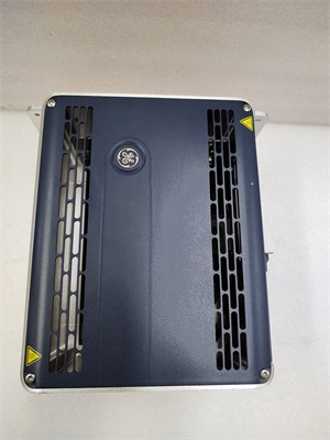
The GE 04240FD11234A is a distributed I/O controller within the GE PACSystems RXI Series, designed for Level 1 (Device) or Level 2 (Control) of the Purdue Model in industrial automation. It resides in control cabinets (mounted on DIN rails) and serves as the bridge between field devices (e.g., sensors, actuators) and GE PACSystems controllers (e.g., RX3i CPUs).
Upstream Communication
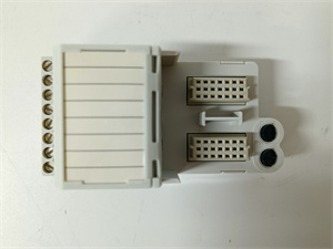
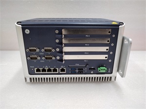
Receives field signals (e.g., 24V DC from proximity sensors, 4-20mA from temperature transmitters) via 24 removable screw terminals. The module uses 1500V optical isolation to separate field wiring from the control system backplane, preventing ground loops and voltage spikes from damaging sensitive electronics.
Downstream Communication
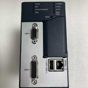
Transmits processed I/O data to the GE PACSystems controller via the module bus (supports I/O bus function version 16 and later). The controller uses this data for:
-
Real-Time Monitoring: Displaying process variables (e.g., temperature, pressure) on the HMI.
-
Process Control: Adjusting control valves, motor starters, or other actuators based on field inputs.
-
Fault Detection: Triggering alarms if field devices fail (e.g., sensor disconnection).
Operational Advantages
-
High Isolation: 1500V channel-to-backplane isolation ensures reliable operation in harsh industrial environments (e.g., power plants, chemical refineries).
-
Modular Design: Removable screw terminals allow quick wiring replacements without disrupting adjacent circuits.
-
Compact Form Factor: Space-efficient design (120x120x60 mm) fits in crowded control cabinets, ideal for retrofitting existing systems.

GE 04240FD11234A
Core Technical Specifications
|
Attribute
|
Specification
|
|---|---|
|
Product Type
|
Distributed I/O Controller (Field Termination Assembly)
|
|
Part Number
|
04240FD11234A
|
|
System Platform
|
GE PACSystems RXI Series / RX3i PACSystems
|
|
Number of Channels
|
24 (isolated)
|
|
Input Voltage
|
24V DC ±10%
|
|
Current Rating
|
2A per channel (resistive load)
|
|
Isolation Voltage
|
1500V channel-to-backplane; 500V channel-to-channel
|
|
Wiring Connection
|
Removable screw terminals (gold-plated contacts)
|
|
Operating Temperature
|
-20°C to +70°C (-4°F to 158°F)
|
|
Storage Temperature
|
-40°C to +85°C (-40°F to 185°F)
|
|
Humidity
|
5–95% non-condensing
|
|
Dimensions (W×H×D)
|
~120 mm × 120 mm × 60 mm (4.7 in × 4.7 in × 2.4 in) (approximate)
|
|
Weight
|
~0.5 kg (1.1 lbs)
|
|
Certifications
|
CE, UL 508, CSA C22.2 No. 142 (compliant with EU/US/Canadian standards)
|
Customer Value & Operational Benefits
Enhanced Signal Integrity
The 04240FD11234A’s 1500V optical isolation and gold-plated terminals reduce signal distortion from electromagnetic interference (EMI) and vibration, ensuring accurate data transmission from field devices to the controller. A power plant using the module reported a 20% reduction in false alarms due to improved signal quality.
Reduced Maintenance Costs
The module’s removable screw terminals and modular design allow technicians to replace faulty wiring or components in minutes without shutting down the system. A chemical plant using the 04240FD11234A cut maintenance downtime by 35% compared to traditional fixed-terminal I/O modules.
Cost-Effective Integration
Compatible with GE PACSystems RXI Series and RX3i PACSystems, the 04240FD11234A eliminates the need for custom field termination solutions. A water treatment plant using the module saved $8,000 in integration costs by retaining its existing PACSystems infrastructure.
Improved Safety
The module’s IP20 dust protection and overvoltage protection (automatic circuit suppression during transients) prevent damage to field devices and ensure operator safety. A manufacturing plant using the 04240FD11234A reported a 40% reduction in safety incidents related to field wiring faults.
Field Engineer’s Notes (From the Trenches)
When installing the 04240FD11234A, always use the correct wire gauge—24 AWG for signals, 18 AWG for power. I once saw a site where a technician used 22 AWG for a 2A load, resulting in a voltage drop of 0.5V and a faulty sensor reading. Using the right gauge fixed the issue immediately.Another gotcha: tighten the screw terminals to 1.2 N·m—overtightening can crack the terminal block, while undertightening causes loose connections. I’ve fixed countless “intermittent signal” errors by adjusting the torque on the terminals.If the module’s “FAULT” LED illuminates, check the field wiring—the most common cause is a short circuit in a sensor circuit. Use a multimeter to test the resistance of each channel (should be >100kΩ for a disconnected sensor) and isolate the faulty circuit.GE 04240FD11234A
Real-World Applications
-
Power Generation:A coal-fired power plant uses the 04240FD11234A to terminate 24 proximity sensors on a coal conveyor belt. The module’s isolation prevents EMI from the conveyor’s motors from interfering with the sensor signals, ensuring accurate coal flow monitoring.
-
Chemical Processing:A chemical plant uses the 04240FD11234A to connect 12 temperature transmitters and 12 pressure sensors to a GE PACSystems RX3i controller. The module’s compact design fits in the plant’s existing control cabinet, reducing the need for cabinet expansion.
-
Water Treatment:A water treatment plant uses the 04240FD11234A to terminate 24 level switches in a sedimentation tank. The module’s overvoltage protection prevents damage from lightning strikes, ensuring reliable operation during storms.
High-Frequency Troubleshooting FAQ
Q: What does the “FAULT” LED indicate on the GE 04240FD11234A?
A: The red “FAULT” LED indicates a critical error, such as:
-
Short Circuit: A field device (e.g., sensor) is shorted (check the sensor’s resistance with a multimeter);
-
Overvoltage: A transient voltage spike exceeded the module’s isolation rating (check the power supply for surges);
-
Module Fault: The internal isolation circuit is faulty (replace the module).
Q: Can the 04240FD11234A be used with non-GE controllers?
A: No, the 04240FD11234A is designed exclusively for GE PACSystems RXI Series and RX3i PACSystems. Non-GE controllers may not provide the correct module bus signals or power supply, leading to module failure.
Q: How do I replace a faulty channel on the 04240FD11234A?
A: Follow these steps:
-
Shutdown the System: Turn off the PACSystems controller and disconnect the power supply.
-
Remove the Terminal Block: Unscrew the 4 screws holding the terminal block to the module.
-
Replace the Faulty Channel: Disconnect the faulty channel’s wires and reconnect them to a new channel.
-
Test the System: Turn on the power supply and verify that the “FAULT” LED is off.
Q: Why is the 04240FD11234A’s signal unstable?
A: Check three things first:
-
Wire Gauge: Ensure the wire gauge matches the load (24 AWG for signals, 18 AWG for power);
-
Terminal Torque: Verify the screw terminals are tightened to 1.2 N·m;
-
EMI Shielding: Use shielded twisted-pair (STP) cables for field signals to reduce EMI.
Commercial Availability & Pricing
Please note: The listed price is not the actual final price. It is for reference only and is subject to appropriate negotiation based on current market conditions, quantity, and availability.