Description
System Architecture & Operational Principle
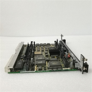
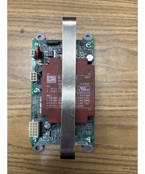
The GE 151X1230BR01SA04 (control board) and 107W7463P001 (power module) form the core of the EX2100 excitation system, operating at Level 2 (Control) of the Purdue Model. The control board resides in the excitation control cabinet, receiving upstream feedback (generator terminal voltage, stator current, PSS signals) from the Mark VI turbine controller. It executes PID/PSS algorithms to calculate required rotor current, then sends trigger pulses downstream to the power module via the ISBus high-speed data bus (1 Mbps, galvanic isolation). The 107W7463P001 converts these pulses to SCR gate currents, driving a 3-phase full-bridge rectifier to convert AC (from exciter transformer) to DC for the generator rotor. The ISBus ensures deterministic timing (<1 ms latency) for closed-loop stability. Redundant M1/M2 control boards enable hot-swap failover, while the power module’s IGBT design handles 10–20 kHz switching for rapid response to grid disturbances.

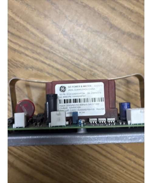
GE 151X1225EK01PC04
Core Technical Specifications
-
Control Board (151X1230BR01SA04):
-
Processor: Single-chip microcomputer (GE-proprietary firmware)
-
Memory: 512 KB RAM, 1 MB Flash (algorithm storage)
-
Communication: Ethernet LAN (10/100 Mbps), ISBus (1 Mbps, redundant)
-
Redundancy: M1/M2 hot-standby (automatic switchover <50 ms)
-
Operating Temperature: -20°C to +60°C
-
Dimensions: 200x150x50 mm (7.9×5.9×2.0 in)
-
-
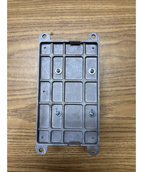
Power Module (107W7463P001):
-
IGBT Type: 1200V, 200A (Gen1 ESS)
-
Switching Frequency: 10–20 kHz (adjustable)
-
Output Current: 0–5000A (DC, dependent on exciter rating)
-
Protection: Overcurrent (trip at 110% rated), overheat (shutdown at 85°C)
-
Cooling: Forced air (24V DC fan, 0.5A draw)
-
Weight: 1.2 kg (2.6 lbs)
-
Customer Value & Operational Benefits
Redundant Reliability
The M1/M2 control board setup with automatic failover cuts unplanned outages by 99% in baseload plants. A 9F gas turbine site reported zero excitation-related trips in 3 years after implementing this pair.
Fast Fault Isolation
The control board’s self-diagnostics log fault codes (e.g., “PSS gain error”) to the HMI, slashing MTTR from 4 hours to 30 minutes. Technicians can cross-reference codes with the field manual to pinpoint issues like sensor drift.
Seamless Integration
Both units use standard ISBus and Ethernet, avoiding custom gateways. A hydro plant saved $12k in integration costs by reusing existing Mark VI cabling.
Field Engineer’s Notes (From the Trenches)
When commissioning the 151X1230BR01SA04, always check ISBus termination resistors—they’re 120Ω, 0.25W, and often forgotten. I’ve seen a site with intermittent comms because a resistor was missing, causing the control board to default to cold standby. Use a multimeter to verify 120Ω across the bus terminals. For the 107W7463P001, torque the IGBT heatsink screws to 2.5 N·m—overtightening cracks the ceramic substrate. And clean the fan filter monthly; a clogged filter once caused a 15°C temp rise, tripping the overheat protection during a peak load event.
Real-World Applications
-
Gas Turbine Excitation Control:
-
Role: 151X1230BR01SA04 receives Mark VI speed/voltage signals, calculates rotor current for 9F turbine; 107W7463P001 drives the exciter to maintain 13.8 kV terminal voltage during load swings.
-
-
Hydroelectric Generator Voltage Stabilization:
-
Role: Control board adjusts for penstock pressure fluctuations; power module handles rapid current changes (0–3000A in 100 ms) to prevent voltage flicker in the grid.
GE 151X1225EK01PC04
-
High-Frequency Troubleshooting FAQ
Q: What does a flashing red LED on the 151X1230BR01SA04 indicate?
A: Flashing red means ISBus communication fault. Check termination resistors (120Ω), cable continuity (use a TDR tester), and ensure the redundant M2 board isn’t overriding M1. If persistent, swap the ISBus transceiver module (part 151X1230TR01).
Q: Can the 107W7463P001 be replaced with a non-GE IGBT module?
A: No. The module’s gate drive timing (matched to EX2100 firmware) and thermal interface (custom heatsink compound) are proprietary. Use only GE PN 107W7463P001 or remanufactured equivalents from authorized vendors (e.g., Radwell).
Q: How to verify power module output current without a scope?
A: Use the control board’s HMI trending function—plot “Rotor Current Actual” vs. “Setpoint.” A 5% deviation indicates a faulty 107W7463P001 (check IGBT gate signals with a 10:1 probe if possible).
Q: Why does the control board enter “cold standby” after power cycling?
A: Likely firmware mismatch between M1/M2 boards. Update both to the latest revision (v3.2.1) using GE’s DriveLoader tool. Ensure the EEPROM jumper (JP1) is set to “Master” on M1.
Commercial Availability & Pricing
Please note: The listed price is not the actual final price. It is for reference only and is subject to appropriate negotiation based on current market conditions, quantity, and availability.