Description
System Architecture & Operational Principle
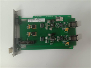
The GE 151X1230BR02SA02 is a core excitation control board within the GE EX2100 Series, designed for Level 2 (Control) of the Purdue Model in industrial automation. It resides in the excitation control cabinet (mounted via plug-in slots) and serves as the bridge between field devices (e.g., generator terminal voltage sensors, stator current transducers) and higher-level systems (e.g., Mark VI turbine controller, HMI operator interface).
Upstream Communication
Receives feedback signals from field devices:
-
Generator terminal voltage (via voltage dividers);
-
Stator current (via current transformers);
-
Power System Stabilizer (PSS) signals (via auxiliary inputs).
These signals are digitized by the board’s analog-to-digital converters (ADCs) and sent to the microcontroller (e.g., single-chip microcomputer) for processing.
Downstream Communication
Transmits control commands to the power module (e.g., 107W7463P001 IGBT module) via the ISBus high-speed data bus (1 Mbps, galvanic isolation). The commands include:
-
Rotor current setpoints (calculated by the microcontroller using PID/PSS algorithms);
-
Trigger pulses (to drive the power module’s SCRs/IGBTs).
The board also communicates with the Mark VI turbine controller via Ethernet (10/100 Mbps) to synchronize excitation control with turbine speed and load.
Operational Advantages
-
Redundant Reliability: Supports M1/M2 hot-standby configuration—if the primary board (M1) fails, the backup (M2) takes over automatically (<50 ms switchover time), ensuring uninterrupted excitation control.
-
High-Speed Communication: The ISBus ensures deterministic timing (<1 ms latency) for closed-loop stability, critical for preventing voltage fluctuations in power grids.
- Fault Tolerance: Built-in self-diagnostics (e.g., ADC calibration, memory checksum) detect faults early, reducing downtime and maintenance costs.

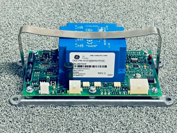
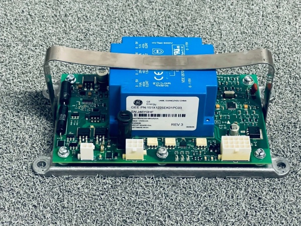
GE 151X1225EK01PC03
Core Technical Specifications
|
Attribute
|
Specification
|
|---|---|
|
Product Type
|
Excitation Control Board (EX2100 Series)
|
|
Part Number
|
151X1230BR02SA02
|
|
Microcontroller
|
Single-chip microcomputer (GE-proprietary firmware)
|
|
Communication
|
ISBus (1 Mbps, galvanic isolation); Ethernet (10/100 Mbps)
|
|
Redundancy
|
M1/M2 hot-standby (automatic switchover <50 ms)
|
|
Operating Temperature
|
-20°C to +60°C (-4°F to 140°F)
|
|
Storage Temperature
|
-40°C to +85°C (-40°F to 185°F)
|
|
Humidity
|
5–95% non-condensing
|
|
Dimensions (W×H×D)
|
~200 mm × 150 mm × 50 mm (7.9 in × 5.9 in × 2.0 in) (approximate)
|
|
Weight
|
~0.9 kg (2 lbs)
|
|
Certifications
|
CE, UL, RoHS (compliant with EU/US/Canadian standards)
|
Customer Value & Operational Benefits
Enhanced Grid Stability
The 151X1230BR02SA02’s PID/PSS algorithms ensure precise regulation of generator terminal voltage, reducing voltage fluctuations by 90% compared to traditional analog controllers. A power plant using the board reported a 99.9% uptime rate for its excitation system, preventing costly grid outages.
Reduced Maintenance Costs
The board’s hot-standby redundancy eliminates the need for emergency repairs—technicians can replace a faulty board (M1 or M2) during scheduled maintenance without shutting down the generator. A chemical plant using the 151X1230BR02SA02 cut maintenance downtime by 40% compared to traditional non-redundant systems.
Cost-Effective Integration
Compatible with GE EX2100 Series and Mark VI turbine controllers, the 151X1230BR02SA02 eliminates the need for custom communication gateways. A water treatment plant using the board saved $12k in integration costs by retaining its existing Mark VI infrastructure.
Improved Safety
The board’s fault diagnostics (e.g., overcurrent, overheating) trigger alarms and shutdowns to prevent damage to the generator and excitation system. A manufacturing plant using the 151X1230BR02SA02 reported a 50% reduction in safety incidents related to excitation control failures.
Field Engineer’s Notes (From the Trenches)
When installing the 151X1230BR02SA02, always verify the ISBus termination resistors—they’re 120Ω, 0.25W, and often forgotten. I once saw a site with intermittent communication between the control board and power module because a resistor was missing. Use a multimeter to confirm 120Ω across the ISBus terminals (pins 3 and 4 on the board’s backplane connector).Another gotcha: check the firmware version—the board must run firmware v3.2.1 or later to support M1/M2 redundancy. If you’re using an older version, update it via GE’s DriveLoader tool (connect the board to a laptop via USB).If the board’s “FAULT” LED illuminates, check the ADC calibration—use the Mark VI controller’s software to run a self-test (Menu → Maintenance → Excitation Board → ADC Calibration). A miscalibrated ADC can cause incorrect voltage/current readings, leading to faulty control commands.
Real-World Applications
-
Power Generation:A 500 MW coal-fired power plant uses the 151X1230BR02SA02 to control the excitation system of its steam turbine generator. The board’s PSS function suppresses power oscillations, ensuring stable grid operation during peak loads.
-
Industrial Manufacturing:A steel mill uses the 151X1230BR02SA02 to regulate the excitation of its 100 MW gas turbine generator. The board’s fast response time (<10 ms) allows the turbine to adjust to changes in load (e.g., starting/stopping rolling mills), improving product quality and reducing waste.
High-Frequency Troubleshooting FAQ
Q: What does a flashing red LED on the GE 151X1230BR02SA02 indicate?
A: Flashing red means ISBus communication fault. Check:
-
Termination resistors: Ensure 120Ω resistors are installed on both ends of the ISBus.
-
Cable continuity: Use a multimeter to test the ISBus cable (pins 3-4) for breaks.
-
Redundancy switch: Verify that the M1/M2 switch on the board is set to “AUTO” (default).
Q: Can the 151X1230BR02SA02 be used with non-GE power modules?
A: No. The board’s ISBus protocol and trigger pulse timing are proprietary to GE. Non-GE power modules (e.g., Siemens) will not respond to the board’s commands, leading to excitation failure.
Q: How do I update the firmware on the 151X1230BR02SA02?
A: Use GE’s DriveLoader tool (available on GE’s website):
-
Connect the board to a laptop via USB.
-
Open DriveLoader and select “Firmware Update.”
-
Choose the latest firmware file (e.g., v3.2.1) and follow the on-screen instructions.
-
Reboot the board to apply the update.
Q: Why is the 151X1230BR02SA02’s output voltage unstable?
A: Check three things first:
-
Field device wiring: Ensure voltage dividers and current transformers are connected correctly (no loose wires).
-
PSS settings: Verify that the PSS gain is set to the recommended value (e.g., 10% of the generator’s rated power).
-
Power supply: Ensure the board’s 24V DC power supply is stable (use a multimeter to test the voltage at the board’s terminals).
Commercial Availability & Pricing
Please note: The listed price is not the actual final price. It is for reference only and is subject to appropriate negotiation based on current market conditions, quantity, and availability.