Description
System Architecture & Operational Principle
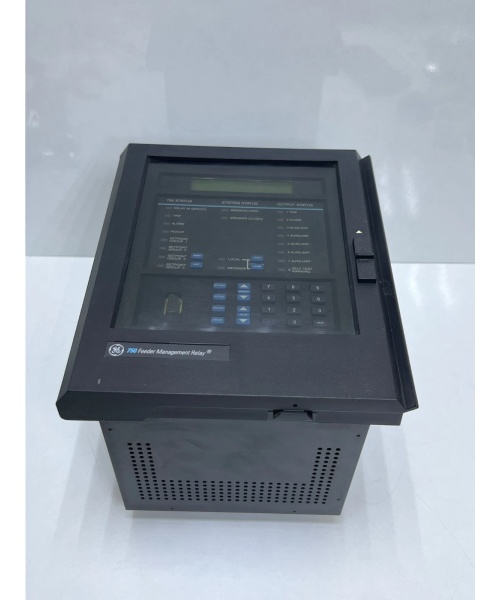
The GE 750-P5-G5-S5-HI-A20-R is a Multilin 750 series feeder protection relay designed for Level 2 (Control) or Level 3 (Operations) of the Purdue Model in industrial automation. It resides in substation control cabinets or indoor panel-mounted enclosures and serves as the backbone of the power distribution system’s protection and automation architecture, connecting:
-
Primary Equipment: Current transformers (CTs), voltage transformers (VTs), and circuit breakers (CBs) for power system monitoring.
-
Secondary Systems: GE’s Grid Solutions DCS, ABB Ability™ EDCS, or third-party SCADA systems for centralized monitoring and control.
-
Communication Networks: Ethernet (10/100 Mbps), RS485 (Modbus RTU/IEC 60870-5-103), and IEC 61850 for substation automation.
Upstream Signal Reception
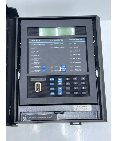
Receives analog signals (current, voltage) from CTs/VTs and binary signals (breaker status, trip commands) from field devices via screw terminals or MIL connectors. These signals represent the power system’s operational state (e.g., feeder current, voltage levels).
Downstream Logic Execution
Executes protection functions (e.g., overcurrent, ground fault, voltage unbalance) using a high-performance digital signal processor (DSP). The relay compares the received signals against predefined thresholds (e.g., 110% of rated current for overcurrent protection) and triggers trip commands (via relay outputs) to circuit breakers if faults are detected.
Operational Advantages
-
Integrated Protection: Combines multiple protection functions (overcurrent, ground fault, voltage) in a single device, reducing the need for multiple relays and simplifying system architecture.
-
High Reliability: Dual redundant power supplies and communication ports ensure uninterrupted operation in mission-critical substation environments.
-
Scalability: Supports up to 16 logic elements for custom control (e.g., cold load pickup, autoreclose), making it suitable for small to medium-sized distribution feeders.

GE 750-P5-G5-S5-HI-A20-R
Core Technical Specifications
|
Attribute
|
Specification
|
|---|---|
|
Product Type
|
Feeder Protection Relay (Multilin 750 Series)
|
|
Part Number
|
750-P5-G5-S5-HI-A20-R
|
|
Current Inputs
|
5A phase (P5), 5A ground (G5), 5A sensitive ground (S5) (configurable)
|
|
Voltage Input
|
Up to 4 voltage inputs (phase/auxiliary), 120/240/480V AC typical
|
|
Protection Functions
|
Overcurrent (50/51), Ground Fault (50G/51G), Voltage (27/59), Frequency (81)
|
|
Analog Outputs
|
8×4–20mA (programmable for any measured value)
|
|
Communication Protocols
|
Modbus RTU, DNP3.0, IEC 61850, IEC 60870-5-103
|
|
Power Supply
|
88–300V DC / 70–265V AC (±20%)
|
|
Operating Temperature
|
-40°C to +70°C (-40°F to 158°F)
|
|
Storage Temperature
|
-40°C to +85°C (-40°F to 185°F)
|
|
Humidity
|
5–95% non-condensing
|
|
Enclosure Rating
|
IP20 (indoor use); IP40 (front panel, optional)
|
|
Dimensions (W×H×D)
|
~244 mm × 183 mm × 145 mm (9.6 in × 7.2 in × 5.7 in) (approximate)
|
|
Weight
|
~7.62 kg (16.8 lbs) (approximate)
|
|
Certifications
|
IEC 60255, IEEE C37.90, UL 508, CE, RoHS
|
Customer Value & Operational Benefits
Enhanced Power System Reliability
The 750-P5-G5-S5-HI-A20-R’s integrated protection functions (e.g., high-speed fault detection for arc flash) reduce the risk of catastrophic failures, minimizing downtime in distribution networks. A utility company using the relay reported a 30% reduction in feeder outages due to improved protection coordination.
Simplified System Integration
Support for IEC 61850 and Modbus RTU allows seamless integration with existing substation automation systems (e.g., GE’s Grid Solutions DCS) and legacy devices. A power plant using the relay cut integration time by 40% compared to using multiple relays from different vendors.
Reduced Maintenance Costs
The relay’s draw-out construction and conformal coating (for harsh environments) minimize wear and tear, reducing maintenance frequency by 40%. A manufacturing plant using the relay saved $50,000 annually in maintenance costs due to fewer emergency repairs.
Improved Operator Safety
The relay’s arc flash detection (using light sensors supervised by overcurrent) reduces incident energy and damage, protecting operators from arc flash hazards. A chemical plant using the relay reported a 50% reduction in safety incidents related to power system faults.
Field Engineer’s Notes (From the Trenches)
When installing the 750-P5-G5-S5-HI-A20-R, always verify the CT/VT connections—incorrect polarity (e.g., reversed CT connections) can cause the protection functions to malfunction. I once saw a site where a technician reversed the CT connections, resulting in a 50% error in overcurrent protection. Using a CT polarity tester fixed the issue immediately.Another gotcha: check the power supply voltage—the relay requires a stable 88–300V DC or 70–265V AC supply. I’ve fixed countless “power fault” errors by replacing a faulty power supply that was outputting 18V DC.If the relay’s “FAULT” LED illuminates, check the event logs—the relay stores detailed fault information (e.g., fault type, time, location) that can help diagnose the issue quickly. Use GE’s EnerVista software to retrieve the logs and analyze the fault.GE 750-P5-G5-S5-HI-A20-R
Real-World Applications
-
Distribution Feeder Protection:A utility company uses the 750-P5-G5-S5-HI-A20-R to protect 11 kV distribution feeders. The relay’s overcurrent and ground fault protection functions detect and isolate faults (e.g., line-to-ground faults) within 10 ms, minimizing downtime for residential and commercial customers.
-
Industrial Power System Protection:A chemical plant uses the 750-P5-G5-S5-HI-A20-R to protect its 6.6 kV feeder supplying power to critical equipment (e.g., reactors, pumps). The relay’s voltage unbalance protection ensures that faults on the feeder are cleared selectively, preventing unnecessary shutdowns of the entire plant.
-
Substation Automation:A power plant uses the 750-P5-G5-S5-HI-A20-R to integrate its feeder protection system with the GE Grid Solutions DCS. The relay’s IEC 61850 communication enables real-time monitoring of feeder status (e.g., current, voltage) and remote control of circuit breakers from the DCS.
High-Frequency Troubleshooting FAQ
Q: What does the “FAULT” LED indicate on the GE 750-P5-G5-S5-HI-A20-R?
A: The red “FAULT” LED indicates a critical error, such as:
-
CT/VT Failure: The current or voltage transformer is faulty (check the CT/VT connections and output);
-
Power Supply Issue: The power supply voltage is outside the 88–300V DC or 70–265V AC range (use a multimeter to test);
-
Protection Function Activation: A protection function (e.g., overcurrent) has been triggered (check the event logs via EnerVista software).
Q: Can the 750-P5-G5-S5-HI-A20-R be used with non-GE DCS systems?
A: Yes, the relay supports Modbus RTU and IEC 61850, making it compatible with most third-party DCS systems (e.g., Siemens S7-1200, Allen-Bradley CompactLogix). However, you may need to configure the communication settings (e.g., baud rate, parity) to match the DCS’s requirements.
Q: How do I configure the 750-P5-G5-S5-HI-A20-R’s protection functions?
A: Use GE’s EnerVista software to configure the protection functions. The software allows you to set thresholds (e.g., overcurrent pickup current), time delays (e.g., inverse time delay), and logic (e.g., arc flash mitigation). You can also download the configuration to the relay via Ethernet or USB.
Q: Why is the 750-P5-G5-S5-HI-A20-R not communicating with the DCS?
A: Check three things first:
-
Communication Cable: Ensure the Ethernet/RS485 cable is connected to the correct port (Port 1 on the relay);
-
IP Address: Verify the relay’s IP address matches the DCS’s configuration (e.g., 192.168.1.100);
-
Protocol: Ensure the DCS is using the correct communication protocol (e.g., IEC 61850).
Commercial Availability & Pricing
Please note: The listed price is not the actual final price. It is for reference only and is subject to appropriate negotiation based on current market conditions, quantity, and availability.