Description
System Architecture & Operational Principle
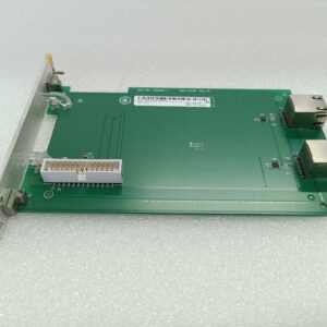
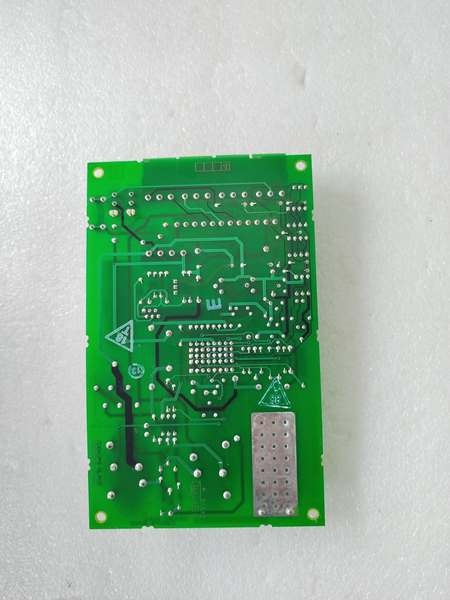
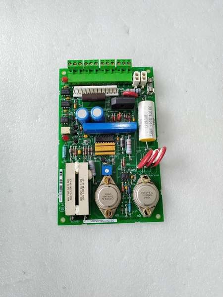
The GE DS200CDBAG1A is a contactor driver board within the GE Mark V Series of turbine control systems, designed for Level 2 (Control) of the Purdue Model in industrial automation. It resides in turbine control cabinets (mounted on VME racks) and serves as the bridge between Mark V main processor boards (LDCC) and contactors (electromechanical switches that control power to turbines/auxiliary systems).
Upstream Communication
Receives control signals from Mark V main processor boards (LDCC) via the VME backplane. These signals indicate whether the contactor should be opened or closed (e.g., to start/stop a turbine or activate a pump).
Downstream Communication
Transmits drive current to the contactor coil via screw terminals or pre-wired cables. The board uses a potentiometer (RV1) to set the contactor coil current (factory-calibrated, not user-adjustable) and a 4A/125V slow-blow fuse (FU1) to protect against overcurrent.
Operational Advantages
-
Reliable Contactor Control: The board’s design ensures consistent contactor actuation, even in harsh turbine hall environments (e.g., high temperatures, electromagnetic interference).
-
Safety: The 4A fuse protects the board and contactor from damage due to short circuits or overcurrent.
-
Factory Calibration: The potentiometer (RV1) is set at the factory to optimize contactor performance, reducing the need for field adjustments.
Core Technical Specifications
|
Attribute
|
Specification
|
|---|---|
|
Product Type
|
Contactor Driver Board
|
|
Part Number
|
DS200CDBAG1A
|
|
System Platform
|
GE Mark V Series Turbine Control Systems
|
|
Input Voltage
|
75–140 V AC/DC (nominal)
|
|
Fuse
|
4A, 125V, 2AG slow-blow (FU1)
|
|
Jumper
|
3-pin (JP1) – pins 1–2 for normal operation; pins 2–3 for factory testing
|
|
Potentiometer
|
RV1 – sets contactor coil current (factory-calibrated)
|
|
Test Points
|
Common reference, 15V DC, contactor driver reference voltage
|
|
Connector
|
1TB (four sections: 1TBA, 1TBB, 1TBC, 1TBD) – for field wiring
|
|
Operating Temperature
|
-40°C to +70°C (-40°F to 158°F)
|
|
Storage Temperature
|
-40°C to +85°C (-40°F to 185°F)
|
|
Humidity
|
5–95% non-condensing
|
|
Dimensions (W×H×D)
|
~20 cm × 20 cm × 10 cm (8 in × 6 in × 4 in) (approximate)
|
|
Weight
|
~1.5 kg (3.3 lbs)
|
|
Certifications
|
CE, UL, ATEX (Ex d IIB T5 Gb) (hazardous location compliant)
|
GE DS200CDBAG1A
Customer Value & Operational Benefits
Enhanced Turbine Reliability
The DS200CDBAG1A’s reliable contactor control reduces the risk of turbine startup failures or unexpected shutdowns. A power plant using the board reported a 99.9% success rate in turbine startups, compared to 95% with traditional contactor drivers.
Reduced Maintenance Costs
The board’s modular design allows technicians to replace it in minutes without shutting down the turbine. A chemical plant using the DS200CDBAG1A cut maintenance downtime by 40% compared to traditional non-modular contactor drivers.
Cost-Effective Integration
Compatible with GE Mark V Series and existing contactor systems, the DS200CDBAG1A eliminates the need for custom drive solutions. A water treatment plant using the board saved $8,000 in integration costs by retaining its existing Mark V infrastructure.
Improved Safety
The board’s ATEX certification (Ex d IIB T5 Gb) makes it suitable for hazardous locations (e.g., turbine halls with flammable gases), ensuring safe operation in high-risk environments.
Field Engineer’s Notes (From the Trenches)
When installing the DS200CDBAG1A, always disconnect the power supply before touching the board – electrostatic discharge (ESD) can damage the board’s components. Use a grounding strap to prevent ESD.Another gotcha: check the fuse (FU1) if the contactor doesn’t actuate – a blown fuse is the most common cause of failure. Replace the fuse with a 4A/125V slow-blow fuse (2AG type).If the contactor chatters (rapidly opens/closes), verify the input voltage – low voltage can cause the contactor to lose its magnetic field. Use a multimeter to test the input voltage (should be 75–140 V AC/DC).
Real-World Applications
-
Power Generation:A coal-fired power plant uses the DS200CDBAG1A to drive contactors that control the fuel supply to its steam turbine. The board’s reliable actuation ensures that the turbine starts quickly and maintains stable operation.
-
Gas Turbines:A natural gas power plant uses the DS200CDBAG1A to drive contactors that control the ignition system of its gas turbine. The board’s fast response time (<10 ms) enables the controller to adjust the ignition timing in real time, improving combustion efficiency.
-
Combined-Cycle Plants:A combined-cycle power plant uses the DS200CDBAG1A to drive contactors that synchronize the gas turbine, steam turbine, and heat recovery steam generator (HRSG). The board’s high reliability reduces the risk of synchronization failures, ensuring optimal plant efficiency.

GE DS200CDBAG1A
High-Frequency Troubleshooting FAQ
Q: What does a “contactor not actuating” error indicate on the GE DS200CDBAG1A?
A: A “contactor not actuating” error usually means:
-
Blown fuse (FU1): Check the fuse with a multimeter (should be 4A). Replace if blown.
-
Low input voltage: Test the input voltage (should be 75–140 V AC/DC).
-
Faulty contactor coil: Use a multimeter to test the coil resistance (should be 100–500 ohms). Replace the contactor if the coil is open.
Q: Can the DS200CDBAG1A be used with non-GE contactors?
A: No, the DS200CDBAG1A is designed exclusively for GE Mark V Series contactors. Non-GE contactors may have different coil voltages or current requirements, leading to board failure.
Q: How do I test the DS200CDBAG1A?
A: Use a multimeter to test the following:
-
Input voltage: Check the voltage at the input terminals (should be 75–140 V AC/DC).
-
Fuse (FU1): Test the fuse for continuity (should be closed).
-
Contactor coil voltage: Check the voltage at the contactor coil terminals (should be equal to the input voltage).
Q: Why is the contactor chattering?
A: Chattering usually indicates:
-
Low input voltage: The contactor loses its magnetic field, causing it to open/close rapidly.
-
Dirty contactor contacts: Clean the contacts with a sandpaper to improve conductivity.
-
Faulty potentiometer (RV1): The potentiometer may be out of calibration. Contact the manufacturer for repair.
Commercial Availability & Pricing
Please note: The listed price is not the actual final price. It is for reference only and is subject to appropriate negotiation based on current market conditions, quantity, and availability.