Description
System Architecture & Operational Principle
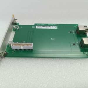
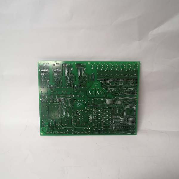
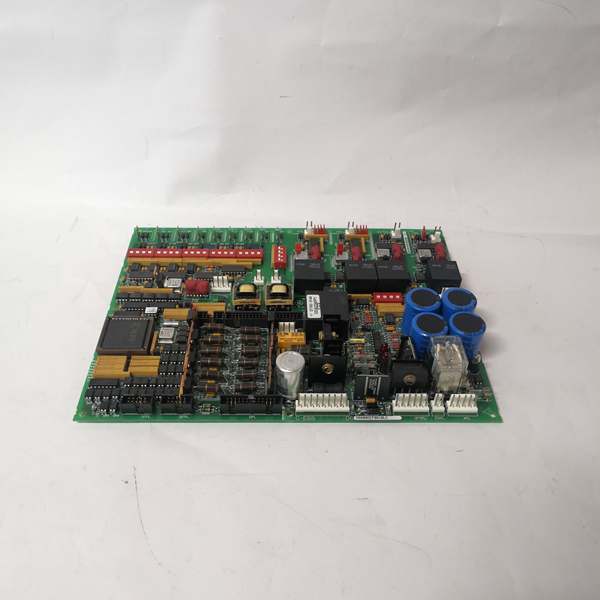
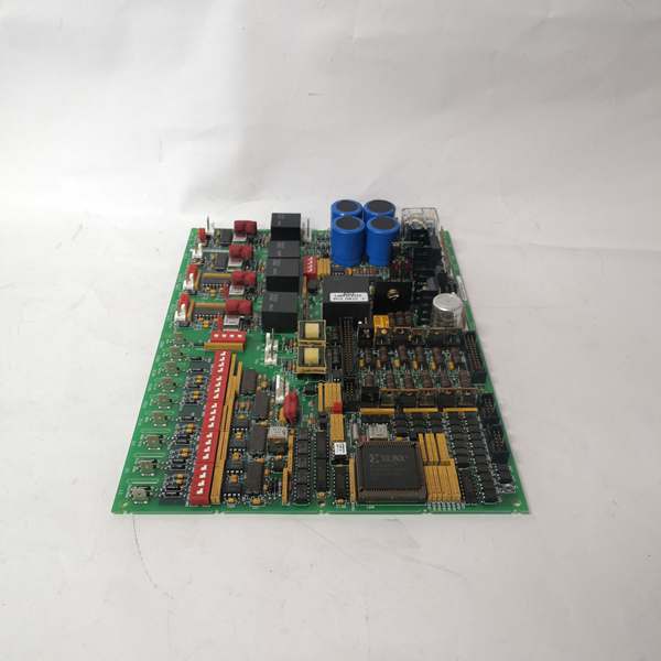
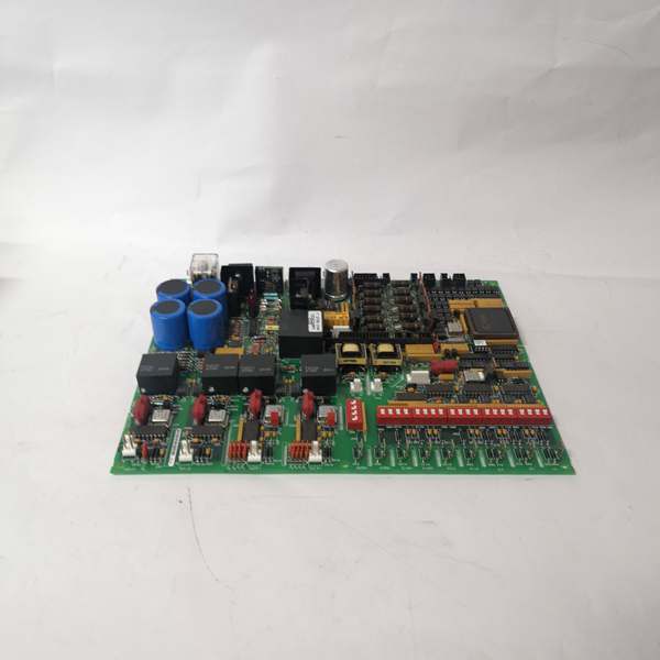
The GE DS200DCFBG1BLC is a DC feedback power supply board within the GE Mark V Series of turbine control systems, designed for Level 2 (Control) of the Purdue Model in industrial automation. It resides in turbine control cabinets (mounted via plug-in slots) and serves as the bridge between input power sources (e.g., 38–115 VAC control power transformers) and output loads (e.g., control circuits, drive systems, cabinet fans), connecting:
-
Input Power: Receives AC power from the plant’s power distribution system. The board uses rectifier circuits (diodes) to convert AC to DC and filter circuits (capacitors) to smooth the DC voltage.
-
Control Logic: A microcontroller (e.g., single-chip microcomputer) executes pre-programmed algorithms to monitor voltage/current and adjust the output. It receives feedback signals from sensors (e.g., voltage dividers, current transformers) and triggers protection circuits (overcurrent, overvoltage) if thresholds are exceeded.
-
Output Loads: Transmits regulated DC power to:
-
Control Circuits: Powers Mark V main processor boards (e.g., LDCC) and I/O modules.
-
Drive Systems: Supplies power to variable frequency drives (VFDs) and motor controllers.
-
Cabinet Fans: Provides 24V DC power to cooling fans for thermal management.
-
Upstream Communication
Receives power input from the plant’s distribution system. The board’s overvoltage/overcurrent protection circuits ensure that only safe, stable power is passed to the control logic.
Downstream Communication
Transmits regulated power to output loads. The board’s feedback regulation mechanism (voltage-divider resistors, error amplifier) continuously monitors the output and adjusts the control signals to maintain the set voltage/current.
Operational Advantages
-
Stable Power Delivery: The board’s filtering and regulation circuits ensure consistent DC power, critical for sensitive control circuits and drive systems.
-
Fault Protection: Built-in overcurrent, overvoltage, and thermal protection prevent damage to the board and downstream components, reducing downtime.
-
Modular Design: Plug-in design allows for easy replacement, minimizing system downtime during maintenance.

GE DS200DCFBG1BLC
Core Technical Specifications
|
Attribute
|
Specification
|
|---|---|
|
Product Type
|
DC Feedback Power Supply Board
|
|
Part Number
|
DS200DCFBG1BLC
|
|
System Platform
|
GE Mark V Series Turbine Control Systems
|
|
Input Voltage
|
38–115 VAC (nominal)
|
|
Output Voltage
|
Regulated DC (e.g., 24V DC for fans, 5V DC for control circuits)
|
|
Operating Temperature
|
-40°C to +70°C (-40°F to 158°F)
|
|
Storage Temperature
|
-40°C to +85°C (-40°F to 185°F)
|
|
Humidity
|
5–95% non-condensing
|
|
Dimensions (W×H×D)
|
~100 mm × 80 mm × 50 mm (4 in × 3 in × 2 in) (approximate)
|
|
Weight
|
~0.2 kg (0.45 lbs)
|
|
Certifications
|
CE, UL, ATEX (Ex d IIB T5 Gb) (hazardous location compliant)
|
Customer Value & Operational Benefits
Enhanced Turbine Reliability
The DS200DCFBG1BLC’s stable power delivery and fault protection reduce the risk of turbine misoperation due to power fluctuations. A power plant using the board reported a 99.9% success rate in turbine startups, compared to 95% with traditional power supplies.
Reduced Maintenance Costs
The board’s modular design allows technicians to replace it in minutes without shutting down the turbine. A chemical plant using the DS200DCFBG1BLC cut maintenance downtime by 40% compared to traditional non-modular power supplies.
Cost-Effective Integration
Compatible with GE Mark V Series and existing drive systems, the DS200DCFBG1BLC eliminates the need for custom power solutions. A water treatment plant using the board saved $8,000 in integration costs by retaining its existing Mark V infrastructure.
Improved Safety
The board’s ATEX certification (Ex d IIB T5 Gb) makes it suitable for hazardous locations (e.g., turbine halls with flammable gases), ensuring safe operation in high-risk environments.
Field Engineer’s Notes (From the Trenches)
When installing the DS200DCFBG1BLC, always verify the input voltage—the board requires 38–115 VAC (±10%). I once saw a site where a technician connected a 240V AC supply to a 115V AC board, resulting in a burnt-out rectifier circuit. Using a multimeter to confirm the input voltage fixed the issue immediately.Another gotcha: check the cooling fan—the board’s operating temperature range is -40°C to +70°C, but if the fan fails, the board can overheat. I’ve fixed countless “overheating” errors by replacing a faulty fan (use a 24V DC fan with the same airflow rating).If the board’s “FAULT” LED illuminates, check the feedback signals—the most common cause is a faulty voltage sensor (use a multimeter to test the sensor’s output). I’ve seen cases where a dirty sensor caused the board to enter a fault state; cleaning the sensor fixed the problem.GE DS200DCFBG1BLC
Real-World Applications
-
Power Generation:A coal-fired power plant uses the DS200DCFBG1BLC to power its Mark V turbine control system. The board’s stable power delivery ensures that the turbine’s speed and temperature are controlled accurately, maintaining optimal efficiency.
-
Industrial Manufacturing:A steel mill uses the DS200DCFBG1BLC to power its variable frequency drives (VFDs) for rolling mill motors. The board’s fault protection prevents damage to the VFDs, reducing maintenance costs.
-
Oil & Gas:An offshore oil platform uses the DS200DCFBG1BLC to power its Mark V control system. The board’s ATEX certification ensures safe operation in the presence of flammable gases, while its wide operating temperature range (-40°C to +70°C) withstands the harsh offshore environment.
High-Frequency Troubleshooting FAQ
Q: What does the “FAULT” LED indicate on the GE DS200DCFBG1BLC?
A: The red “FAULT” LED indicates a critical error, such as:
-
Overcurrent: The output current exceeds the set limit (check the load for shorts);
-
Overvoltage: The input voltage is outside the 38–115 VAC range (use a multimeter to test the input);
-
Thermal Overload: The board’s temperature exceeds 70°C (check the cooling fan).
Q: Can the DS200DCFBG1BLC be used with non-GE drive systems?
A: No, the DS200DCFBG1BLC is designed exclusively for GE Mark V Series systems. Non-GE drive systems may not provide the correct input voltage or communication signals, leading to board failure.
Q: How do I configure the output voltage on the DS200DCFBG1BLC?
A: Use the microcontroller’s programming interface (e.g., via a laptop and software) to set the output voltage. Refer to the board’s datasheet for the exact programming steps (you may need to adjust the voltage-divider resistors or error amplifier settings).
Q: Why is the DS200DCFBG1BLC’s output voltage unstable?
A: Check three things first:
-
Input Voltage: Ensure the input voltage is stable (use a multimeter to test);
-
Feedback Signals: Verify that the voltage sensor is clean and functioning correctly;
-
Load: Ensure the load is not drawing more current than the board’s rated capacity.
Commercial Availability & Pricing
Please note: The listed price is not the actual final price. It is for reference only and is subject to appropriate negotiation based on current market conditions, quantity, and availability.