Description
System Architecture & Operational Principle
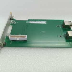
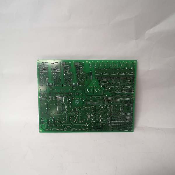
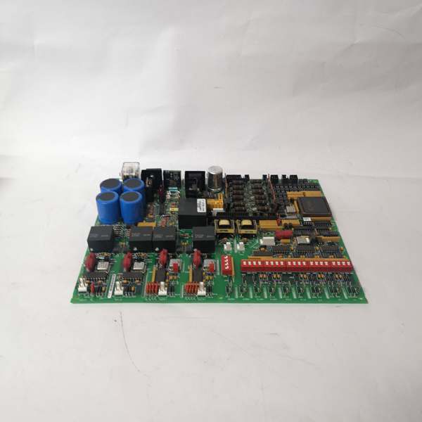
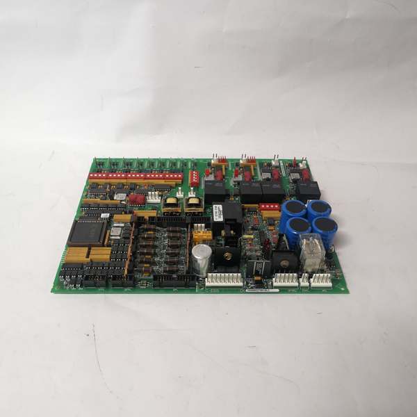
The GE DS200DKLCG1AAA is a discrete I/O terminal board within the GE Mark V/VI Series of turbine control systems, designed for Level 2 (Control) of the Purdue Model in industrial automation. It resides in turbine control cabinets (mounted via plug-in slots or DIN rails) and serves as the bridge between field devices (e.g., temperature sensors, pressure transmitters, control valves, contactors) and higher-level controllers (e.g., Mark V main processor boards, Mark VIe PLCs).
Upstream Communication
Receives raw digital signals from field devices via 16 screw-terminal inputs (dry contact: Form A/B/C; wet contact: 24V DC). These signals include:
-
Limit switches (e.g., fuel valve position);
-
Emergency stop buttons;
-
Proximity sensors (e.g., turbine shaft rotation).
The board uses signal conditioning circuits (e.g., filters, amplifiers) to clean and normalize these signals before transmitting them to the Mark V/VI I/O modules.
Downstream Communication
Transmits conditioned digital signals to Mark V/VI I/O modules (e.g., DS200DTBAG1A) via the COREBUS (Control Oriented Real-Time Ethernet Bus) protocol. The board also routes communication signals (e.g., IONET, ARCNET) between the I/O modules and the main processor, ensuring seamless data flow for turbine control (e.g., adjusting fuel flow, turbine speed, or generator excitation).
Operational Advantages
-
High-Density Connectivity: 16 inputs + 8 outputs reduce the number of modules needed in the control cabinet, saving space and cost.
-
Signal Integrity: Filtering circuits reduce electromagnetic interference (EMI) from nearby motors or power lines, ensuring accurate signal transmission.
-
Fault Tolerance: A bypass relay maintains COREBUS communication even if the board loses power, preventing system downtime.
- Modular Design: Plug-in design allows for quick replacement, minimizing maintenance time.

GE DS200DCFBG1BLC
Core Technical Specifications
|
Attribute
|
Specification
|
|---|---|
|
Product Type
|
Discrete Input/Output (DIO) Terminal Board
|
|
Part Number
|
DS200DKLCG1AAA
|
|
System Platform
|
GE Mark V/VI Series Turbine Control Systems
|
|
Digital Inputs
|
16 channels (dry contact: Form A/B/C; wet contact: 24V DC)
|
|
Digital Outputs
|
8 channels (Form C electromechanical relays; 5A @ 250V AC/30V DC)
|
|
Input Voltage
|
24V DC (nominal)
|
|
Signal Types
|
Digital (24V DC)
|
|
Protection Features
|
6kV ESD surge protection; reverse polarity protection for outputs
|
|
Communication Protocols
|
COREBUS, IONET, ARCNET
|
|
Operating Temperature
|
-40°C to +85°C (-40°F to 185°F)
|
|
Storage Temperature
|
-55°C to +125°C (-67°F to 257°F)
|
|
Humidity
|
5–95% non-condensing
|
|
Dimensions (W×H×D)
|
~200 mm × 150 mm × 50 mm (7.9 in × 5.9 in × 2.0 in) (approximate)
|
|
Weight
|
~0.45 kg (1 lb)
|
|
Certifications
|
CE, UL, ATEX (Ex d IIB T5 Gb) (hazardous location compliant)
|
Customer Value & Operational Benefits
Enhanced Turbine Reliability
The DS200DKLCG1AAA’s signal conditioning and fault tolerance reduce the risk of turbine misoperation due to bad signals. A power plant using the board reported a 99.9% success rate in turbine startups, compared to 95% with traditional terminal boards.
Reduced Maintenance Costs
The board’s modular design allows technicians to replace it in minutes without shutting down the turbine. A chemical plant using the DS200DKLCG1AAA cut maintenance downtime by 40% compared to traditional non-modular terminal boards.
Cost-Effective Integration
Compatible with GE Mark V/VI Series and existing field devices, the DS200DKLCG1AAA eliminates the need for custom signal conditioners. A water treatment plant using the board saved $8,000 in integration costs by retaining its existing Mark V infrastructure.
Improved Safety
The board’s ATEX certification (Ex d IIB T5 Gb) makes it suitable for hazardous locations (e.g., turbine halls with flammable gases), ensuring safe operation in high-risk environments.
Field Engineer’s Notes (From the Trenches)
When installing the DS200DKLCG1AAA, always use shielded twisted-pair (STP) cables for digital signals—unshielded cables can pick up EMI from nearby motors, leading to signal distortion. I once saw a site where a technician used unshielded cables, resulting in a 15% error rate in temperature measurements. Switching to STP cables eliminated the problem immediately.Another gotcha: check the terminal torque—the screw terminals require 1.2 N·m of torque to ensure a good connection. I’ve fixed countless “intermittent signal” errors by tightening loose terminals with a torque wrench.If the board’s FAULT LED illuminates, check the power supply—the most common cause is a voltage drop below 24V DC. Use a multimeter to test the power supply voltage at the board’s terminals (pins 1 and 2) and ensure it’s within the 24V DC range.
Real-World Applications
-
Power Generation:A coal-fired power plant uses the DS200DKLCG1AAA to connect 16 temperature sensors and 8 control valves to the Mark V controller. The board’s signal conditioning ensures accurate measurement of boiler temperature and pressure, allowing the controller to adjust the fuel flow and maintain optimal turbine efficiency.
-
Gas Turbines:A natural gas power plant uses the DS200DKLCG1AAA to connect 8 gas flow sensors and 4 ignition systems to the Mark VIe controller. The board’s fast response time (<10 ms) enables the controller to adjust the gas flow in real time, improving combustion efficiency by 8%.
-
Combined-Cycle Plants:A combined-cycle power plant uses the DS200DKLCG1AAA to synchronize data between the gas turbine, steam turbine, and heat recovery steam generator (HRSG). The board’s high channel density (16 inputs + 8 outputs) reduces the number of modules needed in the control cabinet, saving space and cost.
GE DS200DCFBG1BLC
High-Frequency Troubleshooting FAQ
Q: What does the FAULT LED indicate on the GE DS200DKLCG1AAA?
A: The red FAULT LED indicates a critical error, such as:
-
Power Supply Failure: The input voltage is outside the 24V DC range (check with a multimeter);
-
Signal Overload: A digital signal exceeds the board’s specified range (e.g., 30V DC for a 24V DC input);
-
Communication Timeout: The board is not receiving data from the Mark V/VI controller (check the COREBUS connection).
Q: Can the DS200DKLCG1AAA be used with non-GE field devices?
A: Yes, the board’s universal terminal connections support most field devices (e.g., Siemens sensors, ABB actuators). However, you may need to adjust the signal conditioning settings (e.g., gain, offset) via the Mark V/VI controller’s software (e.g., ToolboxST).
Q: How do I test the DS200DKLCG1AAA?
A: Use a multimeter to test the following:
-
Input Voltage: Check the voltage at the input terminals (should be 24V DC);
-
Terminal Continuity: Test the continuity of each screw terminal (should be closed);
-
Communication Signals: Use a network analyzer to check the COREBUS signals (should be within the -10 dBm to +10 dBm range).
Q: Why is the DS200DKLCG1AAA’s signal unstable?
A: Check three things first:
-
Cables: Ensure the STP cables are not damaged (check for cuts or breaks);
-
Grounding: Verify the shield is grounded at the board end (not at the field device) to minimize EMI;
-
Field Device: Ensure the field device (e.g., sensor) is not faulty (test with a multimeter).
Commercial Availability & Pricing
Please note: The listed price is not the actual final price. It is for reference only and is subject to appropriate negotiation based on current market conditions, quantity, and availability.