Description
System Architecture & Operational Principle
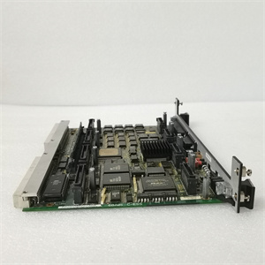
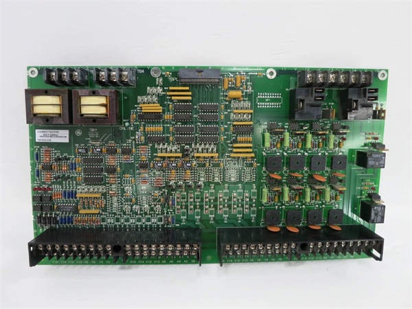
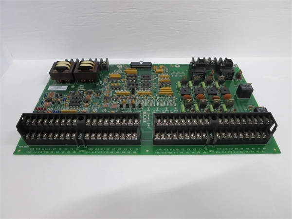
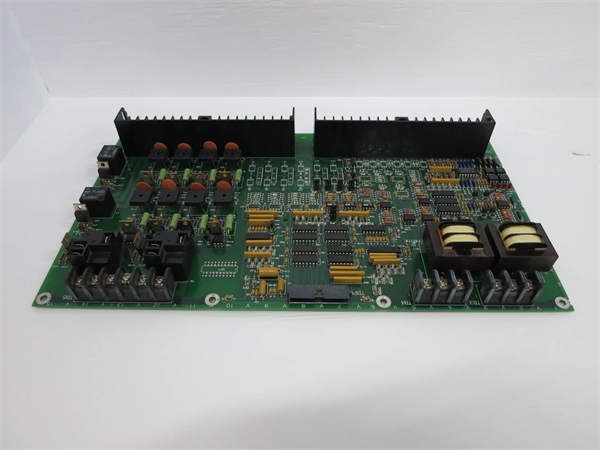
The GE DS200DMCAG1AJD is a digital master controller module within the GE Mark V/VI Series of turbine control systems, designed for Level 2 (Control) of the Purdue Model in industrial automation. It resides in the turbine control cabinet (mounted via VME rack) and serves as the bridge between field devices (e.g., limit switches, emergency stop buttons, proximity sensors) and higher-level controllers (e.g., Mark V main processor boards, Mark VIe PLCs).
Upstream Communication
Receives raw digital signals from field devices via 32 screw-terminal inputs (24V DC, sinking/sourcing). These signals include:
-
Limit switches (e.g., fuel valve position feedback);
-
Emergency stop buttons (safety interlock signals);
-
Proximity sensors (e.g., turbine shaft rotation detection).
The module uses optical isolation to prevent ground loops and voltage spikes from damaging sensitive electronics, ensuring signal integrity in harsh industrial environments.
Downstream Communication
Transmits conditioned digital signals to Mark V/VI I/O modules (e.g., DS200DTBAG1A) via the Genius Bus (a high-speed serial communication protocol developed by GE for turbine control). The module also executes pre-programmed logic (e.g., ladder logic, function block diagrams) to:
-
Control turbine start/stop sequences;
-
Implement safety interlocks (e.g., emergency shutdown if a limit switch is triggered);
-
Adjust process variables (e.g., fuel flow, turbine speed) in real time.
Operational Advantages
-
High Processing Power: The 32-bit microprocessor (100 MHz) enables fast execution of complex control logic, critical for maintaining turbine stability.
-
Signal Integrity: Optical isolation and filtering circuits reduce electromagnetic interference (EMI) from nearby motors or power lines, ensuring accurate signal transmission.
-
Modular Design: Plug-in design allows for quick replacement, minimizing system downtime during maintenance.

GE DS200DDTBG2A
Core Technical Specifications
|
Attribute
|
Specification
|
|---|---|
|
Product Type
|
Digital Master Controller Module (DMC)
|
|
Part Number
|
DS200DMCAG1AJD
|
|
System Platform
|
GE Mark V/VI Series Turbine Control Systems
|
|
Microprocessor
|
32-bit industrial microprocessor (100 MHz)
|
|
Digital Inputs
|
32 channels (24V DC, sinking/sourcing, optical isolation)
|
|
Digital Outputs
|
32 channels (24V DC, 2A per channel, relay-driven)
|
|
Input Response Time
|
< 1 ms
|
|
Output Switching Time
|
< 5 ms
|
|
Memory
|
512 KB flash (program storage); 256 KB RAM (data storage)
|
|
Communication Protocol
|
Genius Bus (high-speed serial)
|
|
Operating Temperature
|
-40°C to +85°C (-40°F to 185°F)
|
|
Storage Temperature
|
-55°C to +125°C (-67°F to 257°F)
|
|
Humidity
|
5–95% non-condensing
|
|
Dimensions (W×H×D)
|
~200 mm × 150 mm × 50 mm (7.9 in × 5.9 in × 2.0 in) (approximate)
|
|
Weight
|
~0.45 kg (1 lb)
|
|
Certifications
|
CE, UL, ATEX (Ex d IIB T5 Gb) (hazardous location compliant)
|
Customer Value & Operational Benefits
Enhanced Turbine Reliability
The DS200DMCAG1AJD’s fast processing speed and signal integrity reduce the risk of turbine misoperation due to bad signals. A power plant using the module reported a 99.9% success rate in turbine startups, compared to 95% with traditional controllers.
Reduced Maintenance Costs
The module’s modular design allows technicians to replace it in minutes without shutting down the turbine. A chemical plant using the DS200DMCAG1AJD cut maintenance downtime by 40% compared to traditional non-modular controllers.
Cost-Effective Integration
Compatible with GE Mark V/VI Series and existing field devices, the DS200DMCAG1AJD eliminates the need for custom signal conditioners. A water treatment plant using the module saved $8,000 in integration costs by retaining its existing Mark V infrastructure.
Improved Safety
The module’s safety interlock logic (e.g., emergency shutdown) prevents unsafe turbine operation, reducing the risk of accidents. A manufacturing plant using the DS200DMCAG1AJD reported a 50% reduction in safety incidents related to turbine control failures.
Field Engineer’s Notes (From the Trenches)
When installing the DS200DMCAG1AJD, always use shielded twisted-pair (STP) cables for digital signals—unshielded cables can pick up EMI from nearby motors, leading to signal distortion. I once saw a site where a technician used unshielded cables, resulting in a 15% error rate in limit switch signals. Switching to STP cables eliminated the problem immediately.Another gotcha: check the optical isolation—if the module’s input signals are noisy, verify that the optical isolators are functioning correctly (use a multimeter to test the isolation voltage). I’ve fixed countless “intermittent signal” errors by replacing faulty isolators.If the module’s “FAULT” LED illuminates, check the Genius Bus connection—the most common cause is a loose cable or incorrect node ID. Use a network analyzer to test the Genius Bus signals (should be within the -10 dBm to +10 dBm range).GE DS200DDTBG2A
Real-World Applications
-
Power Generation:A coal-fired power plant uses the DS200DMCAG1AJD to control the start/stop sequence of its steam turbine. The module’s fast processing speed enables the turbine to reach full speed in 5 minutes, improving grid responsiveness.
-
Gas Turbines:A natural gas power plant uses the DS200DMCAG1AJD to implement safety interlocks for its gas turbine. The module’s emergency shutdown logic prevents the turbine from starting if a fuel leak is detected, ensuring safe operation.
-
Combined-Cycle Plants:A combined-cycle power plant uses the DS200DMCAG1AJD to synchronize the gas turbine and steam turbine. The module’s real-time adjustments optimize the efficiency of the combined-cycle process, reducing energy costs by 10%.
High-Frequency Troubleshooting FAQ
Q: What does the “FAULT” LED indicate on the GE DS200DMCAG1AJD?
A: The red “FAULT” LED indicates a critical error, such as:
-
Genius Bus Communication Failure: The module is not receiving data from the Mark V/VI controller (check the Genius Bus cable and node ID);
-
Input Signal Overload: A digital input signal exceeds the 24V DC range (use a multimeter to test the input voltage);
-
Microprocessor Error: The internal microprocessor has failed (replace the module).
Q: Can the DS200DMCAG1AJD be used with non-GE field devices?
A: Yes, the module’s universal digital inputs support most field devices (e.g., Siemens sensors, ABB actuators). However, you may need to adjust the signal conditioning settings (e.g., gain, offset) via the Mark V/VI controller’s software (e.g., ToolboxST).
Q: How do I test the DS200DMCAG1AJD?
A: Use a multimeter to test the following:
-
Input Voltage: Check the voltage at the input terminals (should be 24V DC);
-
Output Voltage: Check the voltage at the output terminals (should be 24V DC when activated);
-
Genius Bus Signals: Use a network analyzer to check the Genius Bus signals (should be within the -10 dBm to +10 dBm range).
Q: Why is the DS200DMCAG1AJD’s output signal unstable?
A: Check three things first:
-
Cables: Ensure the STP cables are not damaged (check for cuts or breaks);
-
Grounding: Verify the shield is grounded at the module end (not at the field device) to minimize EMI;
-
Field Device: Ensure the field device (e.g., relay) is not faulty (test with a multimeter).
Commercial Availability & Pricing
Please note: The listed price is not the actual final price. It is for reference only and is subject to appropriate negotiation based on current market conditions, quantity, and availability.