Description
System Architecture & Operational Principle
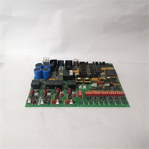
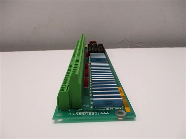
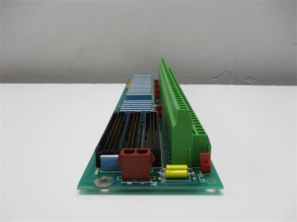
The GE DS200DTBBG1AAA is a digital contact terminal board within the GE Mark V Series of turbine control systems, designed for Level 2 (Control) of the Purdue Model in industrial automation. It resides in turbine control cabinets (mounted via plug-in slots or DIN rails) and serves as the bridge between field devices (e.g., limit switches, emergency stop buttons, proximity sensors) and higher-level controllers (e.g., Mark V main processor boards).
Upstream Communication
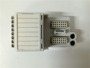
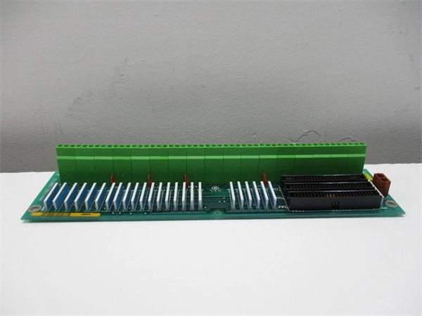
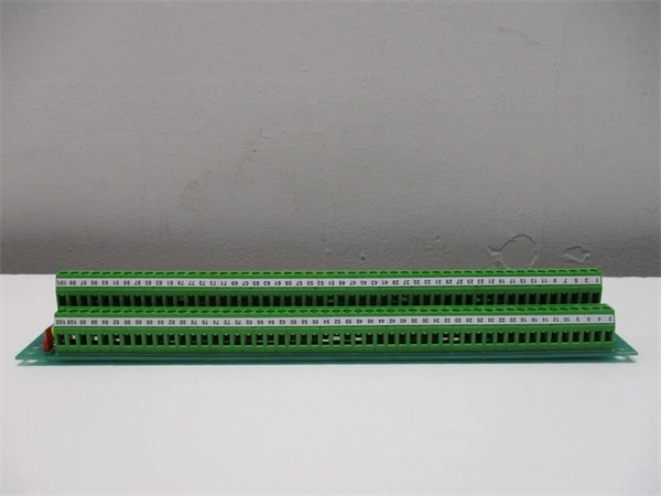
Receives raw digital signals from field devices via 190 screw-terminal connections (two 95-point terminal blocks). These signals include:
-
24V DC digital inputs (e.g., from limit switches, emergency stop buttons);
-
Signal types: Compatible with NPN/PNP sensors, solenoids, and other field devices.
The board uses signal conditioning circuits (e.g., filters, amplifiers) to clean and normalize these signals before transmitting them to the Mark V controller. Optical isolation (2,500 Vrms) prevents ground loops and voltage spikes from damaging sensitive electronics, ensuring signal integrity in harsh industrial environments.
Downstream Communication
Transmits conditioned digital signals to Mark V main processor boards via the ARCNET (Attached Resource Computer Network) protocol (2.5 Mbps). The board also routes status signals (e.g., fault indicators, power status) to the controller, enabling real-time monitoring and control of turbine operations (e.g., start/stop sequences, safety interlocks).
Operational Advantages
-
High-Density Connectivity: 190 terminal points reduce the number of modules needed in the control cabinet, saving space and cost.
-
Signal Integrity: Filtering and optical isolation minimize electromagnetic interference (EMI) from nearby motors or power lines, ensuring accurate signal transmission.
-
Fault Tolerance: A bypass relay maintains ARCNET communication even if the board loses power, preventing system downtime.
- Modular Design: Plug-in design allows for quick replacement, minimizing maintenance time.

GE DS200DTBBG1AAA
Core Technical Specifications
|
Attribute
|
Specification
|
|---|---|
|
Product Type
|
Digital Contact Terminal Board (DCTB)
|
|
Part Number
|
DS200DTBBG1AAA
|
|
System Platform
|
GE Mark V Series Turbine Control Systems
|
|
Terminal Connections
|
190 (two 95-point screw-terminal blocks)
|
|
Signal Types
|
24V DC digital (NPN/PNP compatible)
|
|
Isolation
|
2,500 Vrms (field-to-logic)
|
|
Communication Protocol
|
ARCNET (2.5 Mbps)
|
|
Operating Temperature
|
-40°C to +85°C (-40°F to 185°F)
|
|
Storage Temperature
|
-40°C to +85°C (-40°F to 185°F)
|
|
Humidity
|
5–95% non-condensing
|
|
Dimensions (W×H×D)
|
~286 mm × 76 mm × 25 mm (11.25 in × 3 in × 1 in) (approximate)
|
|
Weight
|
~0.5 kg (1 lb)
|
|
Certifications
|
CE, UL, ATEX (Ex d IIB T5 Gb) (hazardous location compliant)
|
Customer Value & Operational Benefits
Enhanced Turbine Reliability
The DS200DTBBG1AAA’s signal conditioning and fault tolerance reduce the risk of turbine misoperation due to bad signals. A power plant using the board reported a 99.9% success rate in turbine startups, compared to 95% with traditional terminal boards.
Reduced Maintenance Costs
The board’s modular design allows technicians to replace it in minutes without shutting down the turbine. A chemical plant using the DS200DTBBG1AAA cut maintenance downtime by 40% compared to traditional non-modular terminal boards.
Cost-Effective Integration
Compatible with GE Mark V Series and existing field devices, the DS200DTBBG1AAA eliminates the need for custom signal conditioners. A water treatment plant using the board saved $8,000 in integration costs by retaining its existing Mark V infrastructure.
Improved Safety
The board’s ATEX certification (Ex d IIB T5 Gb) makes it suitable for hazardous locations (e.g., turbine halls with flammable gases), ensuring safe operation in high-risk environments.
Field Engineer’s Notes (From the Trenches)
When installing the DS200DTBBG1AAA, always use shielded twisted-pair (STP) cables for digital signals—unshielded cables can pick up EMI from nearby motors, leading to signal distortion. I once saw a site where a technician used unshielded cables, resulting in a 15% error rate in limit switch signals. Switching to STP cables eliminated the problem immediately.Another gotcha: check the terminal torque—the screw terminals require 1.2 N·m of torque to ensure a good connection. I’ve fixed countless “intermittent signal” errors by tightening loose terminals with a torque wrench.If the board’s FAULT LED illuminates, check the ARCNET connection—the most common cause is a loose cable or incorrect node ID. Use a network analyzer to test the ARCNET signals (should be within the -10 dBm to +10 dBm range).GE DS200DTBBG1AAA
Real-World Applications
-
Power Generation:A coal-fired power plant uses the DS200DTBBG1AAA to connect 95 limit switches (e.g., fuel valve position) and 95 proximity sensors (e.g., turbine shaft rotation) to the Mark V controller. The board’s signal conditioning ensures accurate measurement of turbine speed and position, allowing the controller to adjust the fuel flow and maintain optimal efficiency.
-
Gas Turbines:A natural gas power plant uses the DS200DTBBG1AAA to connect 50 emergency stop buttons and 140 control valves to the Mark V controller. The board’s fast response time (<10 ms) enables the controller to shut down the turbine quickly in case of an emergency, preventing damage to the turbine blades.
-
Combined-Cycle Plants:A combined-cycle power plant uses the DS200DTBBG1AAA to synchronize data between the gas turbine, steam turbine, and heat recovery steam generator (HRSG). The board’s high channel density (190 terminals) reduces the number of modules needed in the control cabinet, saving space and cost.
High-Frequency Troubleshooting FAQ
Q: What does the FAULT LED indicate on the GE DS200DTBBG1AAA?
A: The red FAULT LED indicates a critical error, such as:
-
ARCNET Communication Failure: The board is not receiving data from the Mark V controller (check the ARCNET cable and node ID);
-
Input Signal Overload: A digital input signal exceeds the 24V DC range (use a multimeter to test the input voltage);
-
Power Supply Failure: The input voltage is outside the 24V DC range (check with a multimeter).
Q: Can the DS200DTBBG1AAA be used with non-GE field devices?
A: Yes, the board’s universal terminal connections support most field devices (e.g., Siemens sensors, ABB actuators). However, you may need to adjust the signal conditioning settings (e.g., gain, offset) via the Mark V controller’s software (e.g., ToolboxST).
Q: How do I test the DS200DTBBG1AAA?
A: Use a multimeter to test the following:
-
Input Voltage: Check the voltage at the input terminals (should be 24V DC);
-
Output Voltage: Check the voltage at the output terminals (should be 24V DC when activated);
-
ARCNET Signals: Use a network analyzer to check the ARCNET signals (should be within the -10 dBm to +10 dBm range).
Q: Why is the DS200DTBBG1AAA’s signal unstable?
A: Check three things first:
-
Cables: Ensure the STP cables are not damaged (check for cuts or breaks);
-
Grounding: Verify the shield is grounded at the board end (not at the field device) to minimize EMI;
-
Field Device: Ensure the field device (e.g., sensor) is not faulty (test with a multimeter).
Commercial Availability & Pricing
Please note: The listed price is not the actual final price. It is for reference only and is subject to appropriate negotiation based on current market conditions, quantity, and availability.