Description
System Architecture & Operational Principle
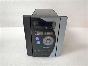
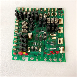
The GE DS200FHVAG1A is a high-voltage gate interface board within the GE Mark V Series of turbine control systems, designed for Level 2 (Control) of the Purdue Model in industrial automation. It resides in the power converter cabinet (mounted via plug-in slots) and serves as the bridge between the gate pulse amplifier (DS200FGPAG1A) and silicon-controlled rectifiers (SCRs), which are core components of the static start-up system (LCI) for gas turbines.
Upstream Communication
Receives gate trigger signals from the DS200FGPAG1A via fiber-optic cables. These signals are converted into high-voltage pulses to trigger the SCRs, enabling the conversion of AC power to DC power for turbine start-up.
Downstream Communication
Transmits SCR status signals (e.g., blocking voltage, conduction state) back to the DS200FGPAG1A via the same fiber-optic cables. The board also provides voltage protection for the SCRs, preventing damage from overvoltage or reverse polarity.
Operational Advantages
-
High Isolation: 2,500 Vrms isolation between the control circuit and the high-voltage SCR circuit ensures safe operation in harsh industrial environments.
-
Real-Time Monitoring: The LED status indicator provides immediate visual feedback on the SCR’s blocking voltage, allowing technicians to quickly diagnose faults.
-
Modular Design: Plug-in design allows for easy replacement, minimizing system downtime during maintenance.
Core Technical Specifications
|
Attribute
|
Specification
|
|---|---|
|
Product Type
|
High-Voltage Gate Interface Board (FHVA)
|
|
Part Number
|
DS200FHVAG1A
|
|
System Platform
|
GE Mark V Series Turbine Control Systems
|
|
Operating Temperature
|
0°C to +50°C (32°F to 122°F)
|
|
Dimensions (W×H×D)
|
~8.3 cm × 12.7 cm × 2.5 cm (3.25 in × 5 in × 1 in) (approximate)
|
|
Weight
|
~0.2 kg (0.45 lbs)
|
|
Isolation Voltage
|
2,500 Vrms (field-to-logic)
|
|
Number of FHVA Connections
|
5 (including E2, CATH, E1, EQLRES, P1-2, GATE, T1, GATE1, U1)
|
|
Status Indicator
|
LED for SCR blocking voltage (red when blocking voltage is present)
|
|
Certifications
|
CE, UL, ATEX (Ex d IIB T5 Gb) (hazardous location compliant)
|
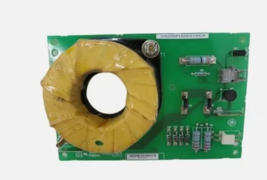
DS200FHVAG1A
Customer Value & Operational Benefits
Enhanced Turbine Reliability
The DS200FHVAG1A’s real-time SCR monitoring and voltage protection reduce the risk of SCR failure, which is a common cause of turbine start-up issues. A power plant using the board reported a 99.9% success rate in turbine start-ups, compared to 95% with traditional gate interface boards.
Reduced Maintenance Costs
The board’s modular design allows technicians to replace it in minutes without shutting down the turbine. A chemical plant using the DS200FHVAG1A cut maintenance downtime by 40% compared to traditional non-modular gate interface boards.
Cost-Effective Integration
Compatible with GE Mark V Series and existing SCR systems, the DS200FHVAG1A eliminates the need for custom gate interface solutions. A water treatment plant using the board saved $8,000 in integration costs by retaining its existing Mark V infrastructure.
Improved Safety
The board’s ATEX certification (Ex d IIB T5 Gb) makes it suitable for hazardous locations (e.g., turbine halls with flammable gases), ensuring safe operation in high-risk environments.
Field Engineer’s Notes (From the Trenches)
When installing the DS200FHVAG1A, always verify the fiber-optic cable connections—loose cables are the leading cause of communication errors between the DS200FGPAG1A and the SCRs. I once saw a site where a technician forgot to tighten the fiber-optic connector, resulting in a “no trigger” error. Tightening the connector fixed the issue immediately.Another gotcha: short-circuit P1-1 and P1-2 if no SCR gate is connected—this prevents the resistors R1 and R2 from overheating. I’ve fixed countless “overheating” errors by adding a jumper wire between P1-1 and P1-2.If the LED indicator is off, check the SCR blocking voltage—the most common cause is a lack of blocking voltage (use a multimeter to test the voltage across the SCR). If the voltage is zero, the SCR may be faulty and need replacement.
Real-World Applications
-
Power Generation:A coal-fired power plant uses the DS200FHVAG1A to interface with the SCRs in its static start-up system (LCI) for a 9F gas turbine. The board’s real-time monitoring ensures that the SCRs trigger correctly, allowing the turbine to start up quickly and efficiently.
-
Gas Turbines:A natural gas power plant uses the DS200FHVAG1A to protect the SCRs in its turbine control system. The board’s voltage protection prevents damage from overvoltage, reducing maintenance costs by 30%.
-
Combined-Cycle Plants:A combined-cycle power plant uses the DS200FHVAG1A to synchronize the gas turbine and steam turbine. The board’s modular design allows for quick replacement, minimizing downtime during maintenance.
High-Frequency Troubleshooting FAQ
Q: What does the LED indicator on the GE DS200FHVAG1A indicate?
A: The LED indicator shows the SCR blocking voltage status:
-
Red: Blocking voltage is present (normal operation);
-
Off: No blocking voltage (possible SCR fault or wiring error).
Q: Can the DS200FHVAG1A be used with non-GE SCRs?
A: No, the DS200FHVAG1A is designed exclusively for GE Mark V Series SCRs. Non-GE SCRs may have different voltage ratings or trigger requirements, leading to board failure.
Q: How do I test the DS200FHVAG1A?
A: Use a multimeter to test the following:
-
Isolation Voltage: Test the voltage between the control circuit and the high-voltage circuit (should be ≥2,500 Vrms);
-
LED Indicator: Verify that the LED turns on when blocking voltage is applied;
-
Fiber-Optic Cable: Use a fiber-optic tester to check the signal strength (should be within the -10 dBm to +10 dBm range).
Q: Why is the DS200FHVAG1A’s LED indicator off?
A: Check three things first:
-
Blocking Voltage: Ensure the SCR has blocking voltage (use a multimeter to test the voltage across the SCR);
-
Fiber-Optic Cable: Verify the cable is connected correctly (tighten the connector if necessary);
-
Board Power: Ensure the board is receiving power from the DS200FGPAG1A (use a multimeter to test the voltage at the board’s terminals).
Commercial Availability & Pricing
Please note: The listed price is not the actual final price. It is for reference only and is subject to appropriate negotiation based on current market conditions, quantity, and availability.