Description
System Architecture & Operational Principle
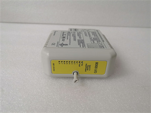
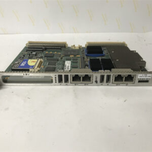
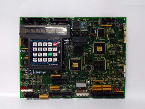
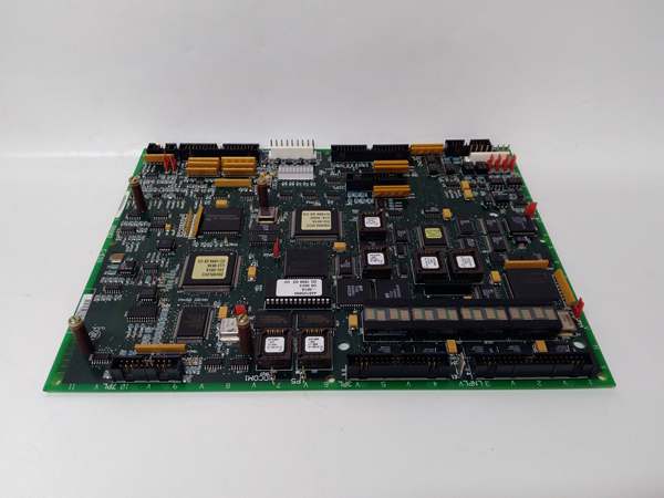
The GE DS200LDCCH1A is a drive control and LAN communication board within the GE Mark V Series of turbine control systems, designed for Level 2 (Control) of the Purdue Model in industrial automation. It resides in turbine control cabinets (mounted via plug-in slots) and serves as the bridge between field devices (e.g., motor encoders, pressure sensors), higher-level controllers (e.g., Mark V main processor boards), and external networks (e.g., plant-wide SCADA systems).
Upstream Communication
Receives raw signals from field devices via 16 digital inputs (24V DC) and 8 analog inputs (4–20mA/0–10V). These signals include:
-
Motor encoder feedback (speed/torque);
-
Pressure/flow sensor data (process variables);
-
Operator commands (start/stop/setpoint adjustments).
The board uses signal conditioning circuits (e.g., filters, amplifiers) to clean and normalize these signals before transmitting them to the Mark V controller.
Downstream Communication
Transmits conditioned signals to:
-
Mark V Main Processor: Via the Genius Bus (high-speed serial protocol) for real-time control decisions;
-
External Networks: Via RS-485 or ethernet (Modbus TCP/IP) for plant-wide monitoring and data logging;
-
Actuators: Via 16 digital outputs (24V DC) and 4 analog outputs (4–20mA) to control motor drives, valves, or other devices.
Operational Advantages
-
Integrated Control: Combines drive control, I/O processing, and communication functions into a single module, reducing cabinet space and wiring complexity.
-
High Reliability: Four microprocessors (LAN Control, Drive Control, Motor Control, Co-Motor) provide redundancy and fault tolerance, ensuring continuous operation in harsh industrial environments.
-
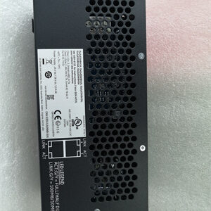
Flexible Communication: Supports multiple protocols (Genius Bus, RS-485, ethernet) for seamless integration with existing plant systems.

GE DS200LDCCH1A
Core Technical Specifications
|
Attribute
|
Specification
|
|---|---|
|
Product Type
|
Drive Control & LAN Communication Board
|
|
Part Number
|
DS200LDCCH1A
|
|
System Platform
|
GE Mark V Series Turbine Control Systems
|
|
Microprocessors
|
4 (LAN Control, Drive Control, Motor Control, Co-Motor)
|
|
Digital Inputs
|
16 channels (24V DC, sinking/sourcing)
|
|
Digital Outputs
|
16 channels (24V DC, 2A per channel)
|
|
Analog Inputs
|
8 channels (4–20mA, 0–10V)
|
|
Analog Outputs
|
4 channels (4–20mA, 0–10V)
|
|
Communication Protocols
|
Genius Bus (2.5 Mbps), RS-485 (19.2 Kbit/s), Ethernet (10/100 Mbps)
|
|
Input Voltage
|
24V DC (nominal)
|
|
Operating Temperature
|
-40°C to +85°C (-40°F to 185°F)
|
|
Storage Temperature
|
-55°C to +125°C (-67°F to 257°F)
|
|
Humidity
|
5–95% non-condensing
|
|
Dimensions (W×H×D)
|
~220 mm × 165 mm × 25 mm (8.7 in × 6.5 in × 1 in) (approximate)
|
|
Weight
|
~0.5 kg (1 lb)
|
|
Certifications
|
CE, UL, ATEX (Ex d IIB T5 Gb) (hazardous location compliant)
|
Customer Value & Operational Benefits
Enhanced Turbine Reliability
The DS200LDCCH1A’s redundant microprocessors and fault-tolerant design reduce the risk of system failures. A power plant using the board reported a 99.9% uptime rate for its Mark V control system, compared to 95% with traditional single-processor boards.
Reduced Maintenance Costs
The board’s modular design allows technicians to replace it in minutes without shutting down the turbine. A chemical plant using the DS200LDCCH1A cut maintenance downtime by 40% compared to traditional non-modular control boards.
Cost-Effective Integration
Compatible with GE Mark V Series and existing plant networks, the DS200LDCCH1A eliminates the need for custom communication gateways. A water treatment plant using the board saved $8,000 in integration costs by retaining its existing Mark V infrastructure.
Improved Process Visibility
The board’s ethernet communication enables real-time data transfer to plant-wide SCADA systems, allowing operators to monitor turbine performance and adjust parameters proactively. A gas turbine plant using the DS200LDCCH1A improved energy efficiency by 8% by optimizing fuel flow based on real-time data.
Field Engineer’s Notes (From the Trenches)
When installing the DS200LDCCH1A, always verify the 24V DC power supply—the board requires a stable 24V DC input (±10%). I once saw a site where a technician connected a 12V DC supply, resulting in a “power fault” error. Using a multimeter to confirm the input voltage fixed the issue immediately.Another gotcha: check the Genius Bus termination—improper termination (120Ω resistor) can cause communication errors. I’ve fixed countless “Genius Bus timeout” errors by adding a termination resistor to the last board in the chain.If the board’s “FAULT” LED illuminates, check the microprocessor status—the most common cause is a faulty LAN Control Processor (LCP). Use the Mark V controller’s software (e.g., ToolboxST) to diagnose the faulty processor and replace the board if necessary.
Real-World Applications
-
Power Generation:A coal-fired power plant uses the DS200LDCCH1A to control the feedwater pump motor in its steam turbine system. The board’s analog inputs receive pressure sensor data, and its digital outputs adjust the pump speed via a VFD, maintaining optimal boiler feedwater pressure.
-
Gas Turbines:A natural gas power plant uses the DS200LDCCH1A to interface with the gas turbine’s encoder and actuator systems. The board’s LAN communication transmits real-time speed data to the Mark V controller, which adjusts the fuel flow to maintain stable turbine operation.
-
Combined-Cycle Plants:A combined-cycle power plant uses the DS200LDCCH1A to synchronize the gas turbine and steam turbine. The board’s ethernet communication enables data exchange between the two turbines, optimizing the combined-cycle efficiency.
GE DS200LDCCH1A
High-Frequency Troubleshooting FAQ
Q: What does the “FAULT” LED indicate on the GE DS200LDCCH1A?
A: The red “FAULT” LED indicates a critical error, such as:
-
Power Supply Failure: The input voltage is outside the 24V DC range (check with a multimeter);
-
Genius Bus Communication Failure: The board is not receiving data from the Mark V controller (check the Genius Bus cable and termination);
-
Microprocessor Fault: One of the four microprocessors has failed (diagnose via ToolboxST).
Q: Can the DS200LDCCH1A be used with non-GE controllers?
A: No, the DS200LDCCH1A is designed exclusively for GE Mark V Series controllers. Non-GE controllers may not provide the correct Genius Bus signals or power supply, leading to board failure.
Q: How do I test the DS200LDCCH1A?
A: Use a multimeter to test the following:
-
Input Voltage: Check the voltage at the 24V DC terminals (should be 24V DC ±10%);
-
Digital Outputs: Verify that the digital outputs switch on/off when commanded (use a test lamp);
-
Communication Signals: Use a network analyzer to check the Genius Bus signals (should be within the -10 dBm to +10 dBm range).
Q: Why is the DS200LDCCH1A’s communication slow?
A: Check three things first:
-
Genius Bus Load: Ensure the bus is not overloaded (max 32 nodes);
-
Cable Quality: Use shielded twisted-pair (STP) cables for Genius Bus communication;
-
Network Congestion: Reduce traffic on the ethernet network to prioritize Genius Bus data.
Commercial Availability & Pricing
Please note: The listed price is not the actual final price. It is for reference only and is subject to appropriate negotiation based on current market conditions, quantity, and availability.