Description
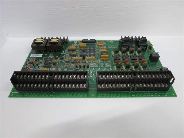
GE DS200NATOG2A Voltage Feedback Scaling Board Product Description
1. Product Overview
The GE DS200NATOG2A is a specialized voltage feedback scaling board, meticulously designed by General Electric as an integral part of the Mark V series, predominantly used in gas turbine control systems. This board plays a pivotal role in ensuring the stable and efficient operation of gas turbines by accurately processing voltage feedback information. It is a key component in the complex network of industrial control systems, especially those related to power generation and large – scale industrial machinery.
2. Detailed Parameter Table
| Parameter Name | Parameter Value |
| Product Model | DS200NATOG2A |
| Manufacturer | General Electric |
| Series | Mark V |
| Product Type | Voltage Feedback Scaling Board |
| Function | Attenuate AC and DC voltages of SCR bridge for accurate voltage feedback derivation |
| Input | Multiple VLG and VLL inputs; each of the five resistor strings has three input stab connectors for a total of 15 input points. Optional wire jumpers (10 in total) for configuration |
| Output | Five strings of outputs connected to a single 20 – pin ribbon header; a VLG output |
| Number of Resistors | Four resistors per string (after replacing two bottom resistors with two wire jumpers in G2 version) |
| Connector | 20 – pin ribbon connector |
| Voltage Protection | Metal oxide varistor (MOV) to prevent output voltage from becoming too high when output ribbon circuit is interrupted |
| Load Resistance Position | Located on the attached gate distribution status board |
| Board Identification | Alphanumeric part number imprinted on the board; e.g., DS200NATOG2A, where “G2” indicates the group variation |
| Operating Temperature Range | – 25°C to + 70°C (ambient); – 40°C to + 85°C (short – term storage, <72h) |
| Weight | Approximately 0.5 kg |
| Dimensions | 8.26 cm × 4.18 cm × 4.62 cm |
| Certifications | CSA, EC, and UL standards for control and known transient |

GE DS200DDGE DS200DDTBG2ATBG2A
3. Product Introduction
3.1 Function in Control Systems
In gas turbine control systems, the DS200NATOG2A board serves as a crucial link between the SCR (Silicon – Controlled Rectifier) bridge and the control unit. Its primary function is to attenuate the AC and DC voltages of the SCR bridge. By doing so, it enables the accurate derivation of bridge voltage feedbacks, which are essential for the control system to precisely regulate the turbine’s speed and power output. For example, in a large – scale power generation plant, the control system needs to constantly monitor and adjust the voltage input to the gas turbine to maintain optimal efficiency. The DS200NATOG2A board ensures that the voltage feedback signals sent to the control unit are accurate, allowing for precise control actions.
3.2 Compatibility and Integration
The DS200NATOG2A board is designed to work in conjunction with two other boards in the LS2100 series: a gate distribution status board and a VME (Versa Module Europa) backplane. This seamless integration within the LS2100 series simplifies the overall control system architecture. The board’s compatibility with these components ensures smooth data flow and coordinated operation. In an industrial automation setup, this integrated approach reduces the complexity of wiring and system configuration, as the three boards work together as a unified unit to manage the voltage feedback and control functions.
3.3 Safety Considerations
The DS200NATOG2A board contains potential electrical hazards. When the board is under power, it is at SCR potential, which can be several thousand volts above ground. Therefore, it is strictly prohibited to touch the board or attempt to make measurements during operation. This safety feature is crucial to protect maintenance personnel and prevent electrical accidents. In a power plant environment, where high – voltage equipment is common, adhering to these safety guidelines is essential to ensure the safety of workers and the reliable operation of the equipment.
4. Core Advantages and Technical Highlights
4.1 High – Precision Voltage Attenuation
The board is equipped with five identical, series – connected strings of precision resistors. Each string can be configured using a selection of three different input stab connectors and two wire jumpers. This flexible configuration allows the board to attenuate input voltages of 6900V, 4200V, 3300V, 2200V, or 1200V, ensuring high – precision voltage attenuation for a wide range of applications. In a power grid with fluctuating voltage levels, the DS200NATOG2A can adjust the input voltage to a suitable level for accurate feedback processing, maintaining the stability of the gas turbine control system.
4.2 Protection Against Voltage Surges
Metal oxide varistors (MOVs) are incorporated into the board’s design. These MOVs prevent the output voltage of each string from becoming too high in case the output ribbon circuit is interrupted while the input voltage is present. This protection mechanism safeguards the board and other components in the control system from voltage surges, enhancing the overall reliability of the system. In an industrial setting where electrical disturbances are common, such as near large motors or in areas with unstable power supplies, the MOV – based protection of the DS200NATOG2A helps prevent damage to the control system components, reducing maintenance costs and downtime.
4.3 Optimized Resistor Configuration
The G2 version of the DS200NATOG2A board replaces two bottom resistors with two wire jumpers, resulting in four resistors per string. This optimized resistor configuration improves the board’s performance and functionality. The four – resistor – per – string design provides better control over the voltage attenuation process, ensuring more accurate and stable voltage feedback. In a complex industrial control system, this enhanced resistor configuration contributes to the overall precision and efficiency of the gas turbine control, leading to improved power generation efficiency.
5. Typical Application Scenarios
5.1 Power Generation Plants
In a gas – fired power generation plant, the DS200NATOG2A board is used to monitor and regulate the voltage feedback from the SCR bridge in the gas turbine control system. The accurate attenuation of AC and DC voltages by the board enables the control system to precisely adjust the turbine’s speed and power output according to the grid’s demand. For instance, during peak – load hours, the control system needs to increase the power output of the gas turbine. The DS200NATOG2A provides accurate voltage feedback, allowing the control system to make the necessary adjustments to the SCR bridge, ensuring stable and efficient power generation.
5.2 Industrial Manufacturing Facilities
In large – scale industrial manufacturing facilities that use gas – powered machinery, the DS200NATOG2A board is employed to maintain the stability of the power supply to the machinery. By accurately processing the voltage feedback, the board helps ensure that the gas – powered equipment operates within the optimal voltage range. In a steel – making plant, for example, gas – fired furnaces require precise voltage control to maintain the correct temperature for the steel – making process. The DS200NATOG2A board plays a vital role in providing the necessary voltage feedback to the control system, ensuring the quality of the steel production.
5.3 Marine Propulsion Systems
Some marine vessels use gas turbines for propulsion. The DS200NATOG2A board is utilized in the control systems of these gas turbines to ensure smooth and efficient operation. The board’s ability to handle voltage feedback in harsh marine environments, with its conformal – coated PCB (moisture/dust resistance) and robust design, makes it suitable for this application. In rough sea conditions, where electrical interference and moisture are common, the DS200NATOG2A continues to provide reliable voltage feedback, ensuring the safe and efficient operation of the marine gas turbine propulsion system.

GE DS200DDTBG2A
6. Related Model Recommendations
6.1 DS200NATOG1A
This is an earlier version of the NATO board. While it has similar functionality to the DS200NATOG2A, the G2 version (DS200NATOG2A) has some improvements, such as the optimized resistor configuration. However, in some legacy systems where cost – effectiveness and compatibility with existing setups are crucial, the DS200NATOG1A may still be a viable option.
6.2 GE VME Backplane (compatible models)
As the DS200NATOG2A works in conjunction with a VME backplane, choosing a compatible VME backplane is essential. GE offers several VME backplane models that are designed to work seamlessly with the DS200NATOG2A, ensuring smooth data transfer and power distribution within the control system.
6.3 Gate Distribution Status Board (compatible models)
Another key component that the DS200NATOG2A pairs with is the gate distribution status board. There are specific GE – designed gate distribution status boards that are optimized for use with the DS200NATOG2A. These boards work together to manage the voltage feedback and control signals, enhancing the overall performance of the gas turbine control system.
7. Installation, Commissioning and Maintenance Instructions
7.1 Installation Preparation
Before installation, it is essential to ensure that the operating environment meets the requirements of – 25°C to + 70°C (ambient) and 5% – 95% RH (non – condensing). The installer should have the necessary tools, including a torque screwdriver (with appropriate torque settings for terminal connections), wire strippers (suitable for the wire gauge used in the installation), and ESD – safe gloves to prevent electrostatic discharge damage to the board. Safety precautions must be strictly followed, such as powering off the entire control system and applying lockout/tagout procedures to prevent accidental energization during installation.
7.2 Installation Process
The DS200NATOG2A board is typically installed in a designated slot on the VME backplane. Secure the board in place using the appropriate mounting hardware, ensuring that it is firmly seated. Connect the input and output wires to the corresponding terminals on the board, following the wiring diagram provided in the product manual. Pay close attention to the polarity of the connections to avoid incorrect voltage application. After wiring, double – check all connections to ensure they are tight and secure.
7.3 Commissioning
During commissioning, power on the control system and use diagnostic tools to check the status of the DS200NATOG2A board. Verify that the board is receiving the correct input voltages and that the output signals are within the expected range. Check for any error messages or abnormal readings on the control system’s monitoring interface. If any issues are detected, refer to the troubleshooting section of the product manual to identify and resolve the problems.
7.4 Maintenance Suggestions
Regular maintenance of the DS200NATOG2A board is crucial for its long – term reliable operation. Periodically inspect the board for any signs of physical damage, such as cracked components or loose connections. Clean the board using a dry, lint – free cloth to remove dust and debris, especially in environments with high dust levels. Check the voltage protection components, such as the MOVs, to ensure they are functioning properly. If any components show signs of wear or damage, replace them with genuine GE – approved spares.
8. Service and Guarantee Commitment
GE offers a comprehensive service and guarantee commitment for the DS200NATOG2A board. The board typically comes with a [X] – year manufacturer’s warranty, covering defects in materials and workmanship under normal operating conditions. In case of a warranty claim, GE provides prompt support, including the supply of replacement boards if necessary.
GE also offers 24/7 technical support to assist customers with installation, commissioning, and troubleshooting. Their team of experts is available to answer any questions and provide guidance to ensure the optimal performance of the DS200NATOG2A board in various applications. Additionally, GE may offer maintenance contracts and on – site service options for customers who require additional support to keep their gas turbine control systems running smoothly.