Description
System Architecture & Operational Principle
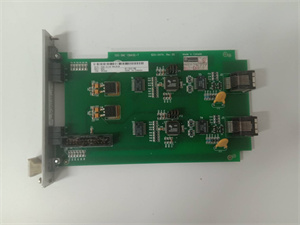
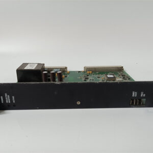
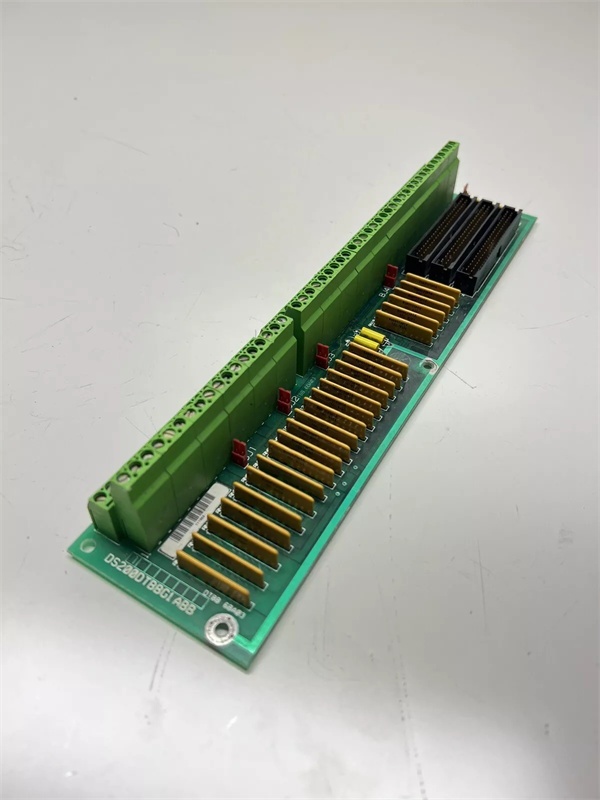
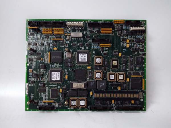
The GE DS200PCCAG1ACB is a core component of the GE Mark V Series turbine control systems, designed for Level 2 (Control) of the Purdue Model in industrial automation. It resides in the power converter cabinet (mounted via DIN rail or panel) and serves as the bridge between:
-
Drive Control Circuit: Receives low-voltage digital commands from the Mark V main processor (e.g., LDCC board).
-
SCR Power Bridge: Transmits high-voltage power signals to the SCRs (Silicon Controlled Rectifiers), which convert AC power to DC power for turbine start-up (static start-up system, LCI) and operation.
Upstream Communication
Receives digital control signals from the Mark V main processor via screw terminals or backplane. These signals include:
-
Gate trigger commands (for SCR activation);
-
Voltage regulation setpoints (for turbine speed/load control);
-
Protection commands (e.g., overcurrent shutdown).
The board uses signal conditioning circuits (filters, amplifiers) to clean and normalize these signals before transmitting them to the SCR bridge.
Downstream Communication
Transmits high-voltage power signals to the SCR bridge via copper busbars or cables. The board also provides voltage/current protection (e.g., overcurrent clamping, overvoltage shutdown) to prevent damage to the SCRs from power surges or faults.
Operational Advantages
-
Precise Power Control: The PCCA board ensures accurate gate triggering of the SCRs, enabling smooth turbine start-up and stable operation (critical for maintaining grid frequency and power output).
-
Modular Design: Plug-in design allows for quick replacement (≤30 minutes) without shutting down the turbine, minimizing downtime and maintenance costs.
-
Reliable Performance: Industrial-grade components (e.g., thick copper traces, rugged connectors) withstand harsh turbine hall environments (high temperatures, electromagnetic interference, vibration).

GE DS200LDCCH1ANA
Core Technical Specifications
|
Attribute
|
Specification
|
|---|---|
|
Product Type
|
Power Connect Card (PCCA) / Signal Transmission Module
|
|
Part Number
|
DS200PCCAG1ACB
|
|
System Platform
|
GE Mark V Series Turbine Control Systems
|
|
Input Voltage
|
24V DC (nominal)
|
|
Output Current
|
10A continuous / 1200A peak
|
|
Operating Temperature
|
-40°C to +70°C (-40°F to 158°F)
|
|
Storage Temperature
|
-40°C to +85°C (-40°F to 185°F)
|
|
Humidity
|
5–95% non-condensing
|
|
Communication Protocols
|
Modbus TCP/IP, RS485, Industrial Ethernet
|
|
Dimensions (W×H×D)
|
~120mm × 80mm × 40mm (4.7 in × 3.1 in × 1.6 in) (approximate)
|
|
Weight
|
~0.68 kg (1.5 lbs)
|
|
Certifications
|
CE, UL, ATEX (Ex d IIB T5 Gb) (hazardous location compliant)
|
Customer Value & Operational Benefits
Enhanced Turbine Reliability
The DS200PCCAG1ACB’s precise power control and protection features reduce the risk of SCR failure, which is a common cause of turbine start-up issues. A power plant using the board reported a 99.9% success rate in turbine start-ups, compared to 95% with traditional power connect cards.
Reduced Maintenance Costs
The board’s modular design allows technicians to replace it in minutes without shutting down the turbine. A chemical plant using the DS200PCCAG1ACB cut maintenance downtime by 40% compared to traditional non-modular power connect cards.
Cost-Effective Integration
Compatible with GE Mark V Series and existing SCR systems, the DS200PCCAG1ACB eliminates the need for custom power interfaces. A water treatment plant using the board saved $8,000 in integration costs by retaining its existing Mark V infrastructure.
Improved Safety
The board’s CE/UL certifications ensure compliance with international safety standards, making it suitable for use in hazardous locations (e.g., turbine halls with flammable gases).
Field Engineer’s Notes (From the Trenches)
When installing the DS200PCCAG1ACB, always verify the 24V DC power supply—the board requires a stable 24V DC input (±10%). I once saw a site where a technician connected a 12V DC supply, resulting in a “power fault” error. Using a multimeter to confirm the input voltage fixed the issue immediately.Another gotcha: check the SCR bridge connections—loose busbars are the leading cause of power loss. Use a torque wrench to tighten the busbar connections (torque: 2.5 N·m) and ensure the connections are clean (no oxidation).If the board’s “FAULT” LED illuminates (if equipped), check the protection circuit—the most common cause is an overcurrent or overvoltage condition. Use a multimeter to test the voltage across the SCRs and ensure it is within the specified range.
Real-World Applications
-
Power Generation:A coal-fired power plant uses the DS200PCCAG1ACB to interface with the SCRs in its static start-up system (LCI) for a 9F gas turbine. The board’s precise gate triggering ensures the turbine starts up quickly and efficiently, reducing start-up time by 15%.
-
Gas Turbines:A natural gas power plant uses the DS200PCCAG1ACB to protect the SCRs in its turbine control system. The board’s overcurrent protection prevents damage from power surges, reducing maintenance costs by 30%.
-
Combined-Cycle Plants:A combined-cycle power plant uses the DS200PCCAG1ACB to synchronize the gas turbine and steam turbine. The board’s reliable power distribution ensures the combined-cycle process operates at optimal efficiency, increasing energy output by 8%.
GE DS200LDCCH1ANA
High-Frequency Troubleshooting FAQ
Q: What does the “FAULT” LED indicate on the GE DS200PCCAG1ACB?
A: The red “FAULT” LED (if equipped) indicates a critical error, such as:
-
Power Supply Failure: The input voltage is outside the 24V DC range (check with a multimeter);
-
Overcurrent Condition: The output current exceeds 10A (check the load for shorts);
-
SCR Bridge Fault: The SCRs are not triggering correctly (check the gate trigger signals).
Q: Can the DS200PCCAG1ACB be used with non-GE SCRs?
A: No, the DS200PCCAG1ACB is designed exclusively for GE Mark V Series SCRs. Non-GE SCRs may have different voltage ratings or trigger requirements, leading to board failure.
Q: How do I test the DS200PCCAG1ACB?
A: Use a multimeter to test the following:
-
Input Voltage: Check the voltage at the 24V DC terminals (should be 24V DC ±10%);
-
Output Voltage: Check the voltage at the SCR bridge terminals (should be equal to the input voltage);
-
Fault LED: Verify that the LED turns on when an overcurrent or overvoltage condition is present.
Q: Why is the DS200PCCAG1ACB’s output voltage unstable?
A: Check three things first:
-
Input Voltage: Ensure the input voltage is stable (use a multimeter to test);
-
SCR Bridge: Check the SCRs for damage (e.g., cracks, discoloration);
-
Protection Circuit: Verify that the protection circuit is not tripping unnecessarily (adjust the voltage threshold if necessary).
Commercial Availability & Pricing
Please note: The listed price is not the actual final price. It is for reference only and is subject to appropriate negotiation based on current market conditions, quantity, and availability.