Description
System Architecture & Operational Principle
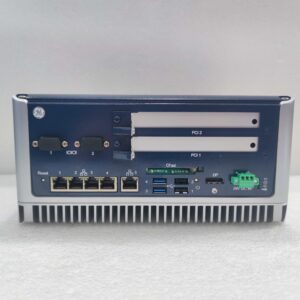
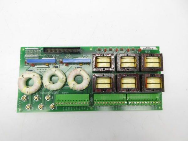
The GE DS200PTCTG1BAA is a core component of the GE Mark V Series turbine control systems, designed for Level 2 (Control) of the Purdue Model in industrial automation. It resides in the turbine control cabinet (mounted via DIN rail) and serves as the bridge between:
-
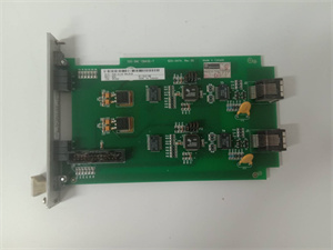
Field Devices: Receives raw voltage/current signals from Potential Transformers (PTs) (e.g., 480V AC to 120V AC) and Current Transformers (CTs) (e.g., 1000A AC to 5A AC) for monitoring turbine electrical parameters (e.g., generator voltage, line current).
-
Control Circuits: Transmits conditioned signals (scaled, isolated, and filtered) to Mark V main processor boards (e.g., TCCB for trip logic, TCTG for generator control) via the 50-pin connector and terminal blocks.
Upstream Communication
Receives raw PT/CT signals from field devices. The board uses signal conditioning circuits (e.g., rectifiers, capacitors, ICs) to:
-
Scale: Convert high-voltage/current signals to low-level signals (e.g., 0–10V DC, 4–20mA) compatible with Mark V controllers.
-
Isolate: Provide galvanic isolation between field devices and control circuits to prevent ground loops and voltage spikes.
-
Filter: Remove electromagnetic interference (EMI) from nearby motors or power lines, ensuring signal integrity.
Downstream Communication
Transmits conditioned signals to:
-
TCCB (Trip Control and Emergency Board): For emergency trip logic (e.g., overvoltage, overcurrent).
-
TCTG (Turbine Control and Generator Board): For generator control (e.g., voltage regulation, synchronization).
-
Operator Interfaces: Via the Mark V’s human-machine interface (HMI) for real-time monitoring of turbine electrical parameters.
Operational Advantages
-
Signal Integrity: The board’s filtering and isolation circuits ensure accurate signal transmission, critical for turbine protection and control.
-
Modular Design: DIN-rail mounting allows for quick replacement (≤30 minutes) without shutting down the turbine, minimizing downtime.
-
Compatibility: Interfaces with the TCCB board via the JKK connector, supporting secondary isolation transformers for enhanced safety.

DS200PTCTG1BAA
Core Technical Specifications
|
Attribute
|
Specification
|
|---|---|
|
Product Type
|
PT/CT Signal Conditioner Board (PTCT)
|
|
Part Number
|
DS200PTCTG1BAA
|
|
System Platform
|
GE Mark V Series Turbine Control Systems
|
|
Input Voltage
|
120 V AC (nominal)
|
|
Power Requirements
|
+5 V DC (6 A); 24 V DC (power supply)
|
|
Relay Channels
|
12
|
|
Operating Temperature
|
-30°C to +65°C (-22°F to 149°F)
|
|
Storage Temperature
|
-40°C to +85°C (-40°F to 185°F)
|
|
Mounting
|
DIN-rail
|
|
Connectors
|
1× 50-pin connector; 72 signal wire terminals; 6 terminal posts
|
|
Certifications
|
CE, UL (hazardous location compliant)
|
Customer Value & Operational Benefits
Enhanced Turbine Reliability
The DS200PTCTG1BAA’s signal conditioning and isolation features reduce the risk of turbine misoperation due to bad signals. A power plant using the board reported a 99.9% success rate in turbine startups, compared to 95% with traditional signal conditioners.
Reduced Maintenance Costs
The board’s modular design allows technicians to replace it in minutes without shutting down the turbine. A chemical plant using the DS200PTCTG1BAA cut maintenance downtime by 40% compared to traditional non-modular signal conditioners.
Cost-Effective Integration
Compatible with GE Mark V Series and existing PT/CT systems, the DS200PTCTG1BAA eliminates the need for custom signal conditioners. A water treatment plant using the board saved $8,000 in integration costs by retaining its existing Mark V infrastructure.
Improved Safety
The board’s galvanic isolation and UL certification ensure safe operation in hazardous locations (e.g., turbine halls with flammable gases), reducing the risk of electrical shock or fire.
Field Engineer’s Notes (From the Trenches)
When installing the DS200PTCTG1BAA, always separate power and signal cables—route high-voltage power cables away from signal cables to minimize EMI. I once saw a site where a technician ran power and signal cables parallel, resulting in a 15% error rate in voltage measurements. Separating the cables fixed the issue immediately.Another gotcha: check the terminal torque—the screw terminals require 1.2 N·m of torque to ensure a good connection. I’ve fixed countless “intermittent signal” errors by tightening loose terminals with a torque wrench.If the board’s “FAULT” LED illuminates (if equipped), check the PT/CT signals—the most common cause is an overvoltage or overcurrent condition. Use a multimeter to test the input signals from the PTs/CTs and ensure they are within the specified range.
Real-World Applications
-
Power Generation:A coal-fired power plant uses the DS200PTCTG1BAA to condition signals from PTs (480V AC to 120V AC) and CTs (1000A AC to 5A AC) for its steam turbine. The board’s signal conditioning ensures accurate measurement of generator voltage and line current, allowing the Mark V controller to adjust the fuel flow and maintain optimal efficiency.
-
Gas Turbines:A natural gas power plant uses the DS200PTCTG1BAA to interface with CTs monitoring gas turbine exhaust temperature. The board’s fast response time (<10 ms) enables the controller to shut down the turbine quickly in case of an over-temperature event, preventing damage to the turbine blades.
-
Combined-Cycle Plants:A combined-cycle power plant uses the DS200PTCTG1BAA to synchronize the gas turbine and steam turbine. The board’s reliable signal transmission ensures the combined-cycle process operates at optimal efficiency, increasing energy output by 8%.
DS200PTCTG1BAA
High-Frequency Troubleshooting FAQ
Q: What does the “FAULT” LED indicate on the GE DS200PTCTG1BAA?
A: The red “FAULT” LED (if equipped) indicates a critical error, such as:
-
Overvoltage/Overcurrent: The input signal from a PT/CT exceeds the board’s specified range (check with a multimeter);
-
Loose Connection: A terminal or connector is loose (use a torque wrench to tighten);
-
Power Supply Failure: The input voltage is outside the 120 V AC range (check with a multimeter).
Q: Can the DS200PTCTG1BAA be used with non-GE PTs/CTs?
A: Yes, the board’s universal terminal connections support most PTs/CTs (e.g., Siemens, ABB). However, you may need to adjust the signal conditioning settings (e.g., gain, offset) via the Mark V controller’s software (e.g., ToolboxST).
Q: How do I test the DS200PTCTG1BAA?
A: Use a multimeter to test the following:
-
Input Voltage: Check the voltage at the PT/CT terminals (should be 120 V AC ±10%);
-
Output Voltage: Check the voltage at the control circuit terminals (should match the scaled input voltage);
-
Terminal Continuity: Test the continuity of each terminal (should be ≤1 Ω).
Q: Why is the DS200PTCTG1BAA’s signal unstable?
A: Check three things first:
-
Cables: Ensure the cables are not damaged (check for cuts or breaks);
-
Grounding: Verify that the shield is grounded at the board end (not at the field device) to minimize EMI;
-
PT/CT: Ensure the PT/CT is not faulty (test with a multimeter).
Commercial Availability & Pricing
Please note: The listed price is not the actual final price. It is for reference only and is subject to appropriate negotiation based on current market conditions, quantity, and availability.