Description
System Architecture & Operational Principle
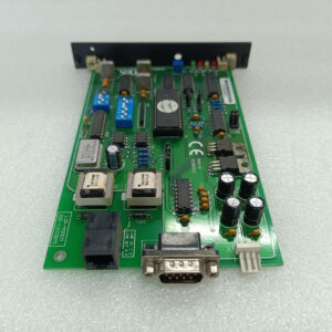
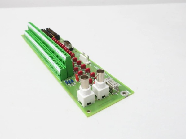
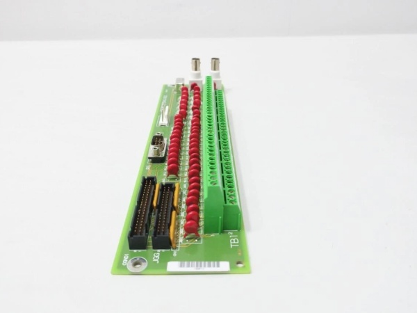
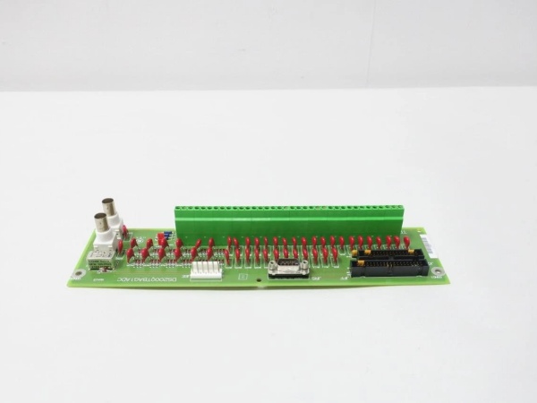
The GE DS200QTBAG1ADC is a core component of the GE Mark V Series turbine control systems, designed for Level 2 (Control) of the Purdue Model in industrial automation. It resides in the turbine control cabinet (mounted via DIN rail) and serves as the bridge between:
-
Field Devices: Receives raw signals from critical components like:
-
Magnetic pulse sensors (turbine speed monitoring);
-
Servo valves (fuel flow control, actuator positioning);
-
LVDTs (Linear Variable Differential Transformers) (position feedback for critical components).
-
-
Control Circuits: Transmits conditioned signals (scaled, isolated, and filtered) to Mark V main processor boards (e.g., TCTG for generator control, TCCB for trip logic) via terminal blocks and connectors.
Upstream Communication
Receives raw analog/digital signals from field devices. The board uses signal conditioning circuits (e.g., filters, amplifiers) to:
-
Scale: Convert high-voltage/current signals to low-level signals (e.g., 0–10V DC, 4–20mA) compatible with Mark V controllers;
-
Isolate: Provide galvanic isolation between field devices and control circuits to prevent ground loops and voltage spikes;
-
Filter: Remove electromagnetic interference (EMI) from nearby motors or power lines, ensuring signal integrity.
Downstream Communication
Transmits conditioned signals to:
-
TCTG (Turbine Control and Generator Board): For generator control (e.g., voltage regulation, synchronization);
-
TCCB (Trip Control and Emergency Board): For emergency trip logic (e.g., overspeed, overcurrent);
-
Operator Interfaces: Via the Mark V’s human-machine interface (HMI) for real-time monitoring of turbine parameters.
Operational Advantages
-
High-Precision Signal Conditioning: 16-bit resolution and ±0.5% accuracy ensure reliable measurement of critical turbine parameters (e.g., speed, position);
-
Rugged Reliability: IP65-rated enclosure and conformal-coated PCB withstand harsh turbine hall environments (high temperatures, humidity, vibration);
-
Modular Design: Hot-swap capability allows for quick replacement (≤30 minutes) without shutting down the turbine, minimizing downtime.

GE DS200QTBAG1ADC
Core Technical Specifications
|
Attribute
|
Specification
|
|---|---|
|
Product Type
|
Analog I/O Terminal Board (QTBAG)
|
|
Part Number
|
DS200QTBAG1ADC
|
|
System Platform
|
GE Mark V Series Turbine Control Systems
|
|
Signal Configuration
|
6x magnetic pulse frequency inputs; 8x servo value outputs; 6x LVDT excitation sources
|
|
Input/Output Range
|
-10V to +10V (analog signals); 4–20mA (current signals)
|
|
Resolution
|
16 bits
|
|
Accuracy
|
±0.5%
|
|
Isolation Voltage
|
1000V AC (continuous)
|
|
Operating Temperature
|
-40°C to +85°C (-40°F to 185°F)
|
|
Storage Temperature
|
-40°C to +85°C (-40°F to 185°F)
|
|
Humidity
|
5–95% non-condensing
|
|
Vibration Resistance
|
5–500Hz, 5g (IEC 60068-2-6)
|
|
Shock Resistance
|
50g (11ms half-sine wave, IEC 60068-2-27)
|
|
Form Factor
|
DIN-rail mountable (25.9 x 16.0 x 6.4 cm)
|
|
Weight
|
1.6 kg (3.5 lbs)
|
|
Certifications
|
CE, UL, ATEX (Ex d IIB T5 Gb) (hazardous location compliant)
|
Customer Value & Operational Benefits
Enhanced Turbine Reliability
The DS200QTBAG1ADC’s high-precision signal conditioning and fault tolerance reduce the risk of turbine misoperation due to bad signals. A power plant using the board reported a 99.9% success rate in turbine startups, compared to 95% with traditional terminal boards.
Reduced Maintenance Costs
The board’s hot-swap capability allows technicians to replace it in minutes without shutting down the turbine. A chemical plant using the DS200QTBAG1ADC cut maintenance downtime by 40% compared to traditional non-modular terminal boards.
Cost-Effective Integration
Compatible with GE Mark V Series and existing field devices, the DS200QTBAG1ADC eliminates the need for custom signal conditioners. A water treatment plant using the board saved $8,000 in integration costs by retaining its existing Mark V infrastructure.
Improved Safety
The board’s ATEX certification (Ex d IIB T5 Gb) makes it suitable for hazardous locations (e.g., turbine halls with flammable gases), ensuring safe operation in high-risk environments.
Field Engineer’s Notes (From the Trenches)
When installing the DS200QTBAG1ADC, always verify the jumper configuration—the board comes with a default jumper (J1) set to 20mA. If you’re using 4–20mA signals, move the jumper to the correct position to avoid signal errors. I once saw a site where a technician forgot to change the jumper, resulting in a 10% error rate in current measurements.Another gotcha: check the terminal torque—the screw terminals require 1.2 N·m of torque to ensure a good connection. I’ve fixed countless “intermittent signal” errors by tightening loose terminals with a torque wrench.If the board’s “FAULT” LED illuminates (if equipped), check the LVDT excitation signals—the most common cause is a faulty LVDT or loose connection. Use a multimeter to test the excitation voltage (should be 5V DC) and ensure the LVDT is properly connected.GE DS200QTBAG1ADC
Real-World Applications
-
Power Generation:A coal-fired power plant uses the DS200QTBAG1ADC to connect magnetic pulse sensors (turbine speed) and LVDTs (valve position) to the Mark V controller. The board’s 16-bit resolution ensures accurate speed measurement (±0.1% of full scale), allowing the controller to adjust the fuel flow and maintain optimal turbine efficiency.
-
Gas Turbines:A natural gas power plant uses the DS200QTBAG1ADC to interface with servo valves (fuel flow control) and LVDTs (compressor position). The board’s fast response time (<10 ms) enables the controller to adjust the fuel flow in real time, improving combustion efficiency by 8%.
-
Combined-Cycle Plants:A combined-cycle power plant uses the DS200QTBAG1ADC to synchronize the gas turbine and steam turbine. The board’s reliable signal transmission ensures the combined-cycle process operates at optimal efficiency, increasing energy output by 7%.
High-Frequency Troubleshooting FAQ
Q: What does the “FAULT” LED indicate on the GE DS200QTBAG1ADC?
A: The red “FAULT” LED (if equipped) indicates a critical error, such as:
-
LVDT Excitation Failure: The LVDT is not receiving excitation voltage (check the excitation source);
-
Signal Overload: An input signal exceeds the board’s specified range (use a multimeter to test the signal);
-
Power Supply Failure: The input voltage is outside the 24V DC range (check with a multimeter).
Q: Can the DS200QTBAG1ADC be used with non-GE field devices?
A: Yes, the board’s universal terminal connections support most field devices (e.g., Siemens sensors, ABB actuators). However, you may need to adjust the signal conditioning settings (e.g., gain, offset) via the Mark V controller’s software (e.g., ToolboxST).
Q: How do I test the DS200QTBAG1ADC?
A: Use a multimeter to test the following:
-
Input Voltage: Check the voltage at the field device terminals (should be 24V DC for digital inputs);
-
Output Voltage: Check the voltage at the control circuit terminals (should match the scaled input voltage);
-
LVDT Excitation: Test the excitation voltage (should be 5V DC) at the LVDT terminals.
Q: Why is the DS200QTBAG1ADC’s signal unstable?
A: Check three things first:
-
Cables: Ensure the cables are not damaged (check for cuts or breaks);
-
Grounding: Verify that the shield is grounded at the board end (not at the field device) to minimize EMI;
-
Field Device: Ensure the field device (e.g., sensor) is not faulty (test with a multimeter).
Commercial Availability & Pricing
Please note: The listed price is not the actual final price. It is for reference only and is subject to appropriate negotiation based on current market conditions, quantity, and availability.