Description
System Architecture & Operational Principle
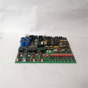
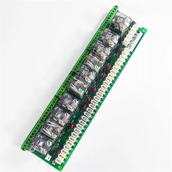
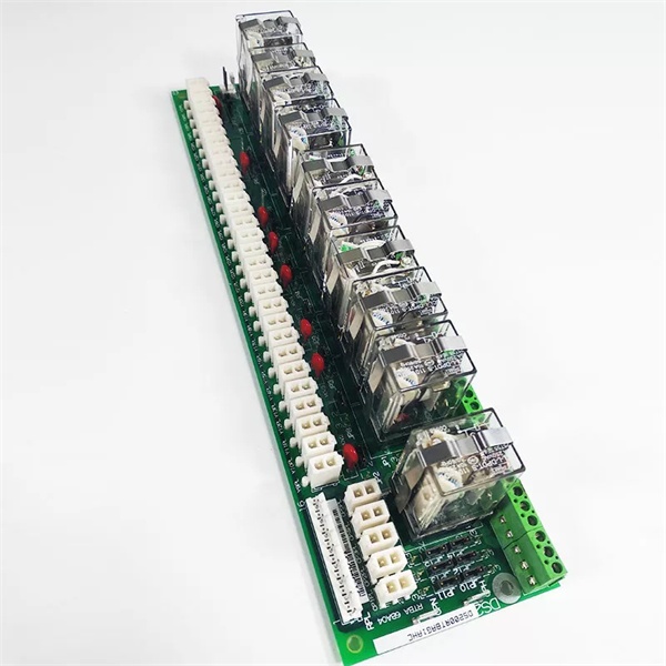
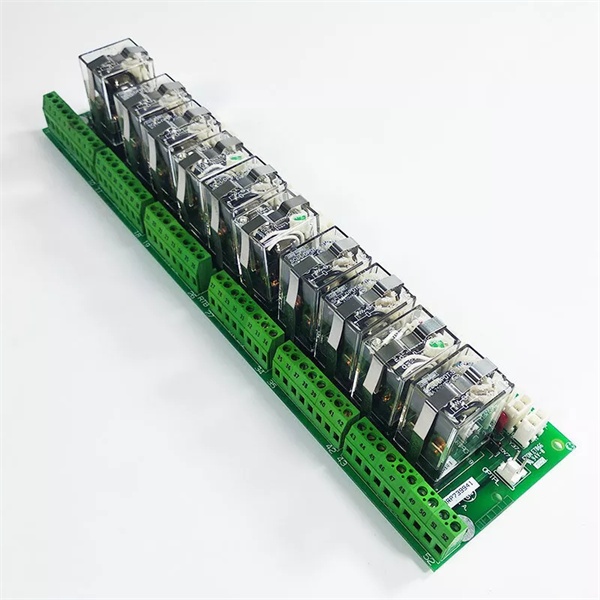
The GE DS200RTBAG1AHC is a core component of the GE Mark V Series turbine control systems, designed for Level 2 (Control) of the Purdue Model in industrial automation. It resides in the turbine control cabinet (panel-mounted) and serves as the bridge between:
-
Digital Output Modules: Receives low-voltage control signals (24V DC) from Mark V main processor boards (e.g., LDCC, TCTG).
-
Field Devices: Transmits high-current switching signals to critical components like:
-
Fuel valves (gas turbine combustion control);
-
Cooling fans (turbine thermal management);
-
Contactor coils (motor/pump control);
-
Alarm indicators (panel-mounted lights/buzzers).
-
Upstream Communication
Receives digital control signals from Mark V main processor boards via screw terminals. The board uses isolation circuits (e.g., optocouplers) to separate low-voltage control signals from high-voltage field circuits, preventing damage to sensitive electronics.
Downstream Communication
Transmits switching signals to field devices via 12 relay outputs (Form C contacts: normally open/normally closed). Each relay channel includes fuse protection (individual fuses per channel) to prevent overcurrent damage.
Operational Advantages
-
High Reliability: Electromechanical relays with 10⁶ mechanical operations lifespan ensure long-term stable operation in harsh industrial environments.
-
Electrical Isolation: 1500V isolation voltage between field and system sides protects sensitive control electronics from voltage transients (e.g., lightning strikes, power surges).
-
Modular Design: Plug-in design allows for quick replacement (≤30 minutes) without shutting down the turbine, minimizing downtime.
Core Technical Specifications
|
Attribute
|
Specification
|
|---|---|
|
Product Type
|
Relay Terminal Board (RTBAG)
|
|
Part Number
|
DS200RTBAG1AHC
|
|
System Platform
|
GE Mark V Series Turbine Control Systems
|
|
Relay Outputs
|
12 channels (Form C contacts: NO/NC)
|
|
Switching Capacity
|
5A @ 250V AC (resistive load); 3A @ 250V AC (inductive load); 5A @ 30V DC
|
|
Coil Voltage
|
24V DC (externally supplied from Mark V backplane)
|
|
Isolation Voltage
|
1500V AC (field-to-system); 1000V AC (channel-to-channel)
|
|
Contact Resistance
|
< 50mΩ (per channel)
|
|
Mechanical Life
|
> 10⁶ operations
|
|
Electrical Life
|
> 10⁵ operations (at rated load)
|
|
Operating Temperature
|
-30°C to +70°C (-22°F to 158°F)
|
|
Storage Temperature
|
-40°C to +85°C (-40°F to 185°F)
|
|
Humidity
|
5–95% non-condensing
|
|
Dimensions (W×H×D)
|
~267 mm × 216 mm × 38 mm (10.5 in × 8.5 in × 1.5 in) (approximate)
|
|
Weight
|
~1.13 kg (2.5 lbs)
|
|
Certifications
|
CE, UL, CSA (hazardous location compliant)
|
GE DS200RTBAG1AHC
Customer Value & Operational Benefits
Enhanced Turbine Reliability
The DS200RTBAG1AHC’s high-quality relays and isolation circuits reduce the risk of field device malfunctions due to signal noise or voltage spikes. A power plant using the board reported a 99.8% success rate in turbine auxiliary system control, compared to 92% with traditional relay boards.
Reduced Maintenance Costs
The board’s modular design and hot-swap capability allow technicians to replace it in minutes without shutting down the turbine. A chemical plant using the DS200RTBAG1AHC cut maintenance downtime by 35% compared to traditional non-modular relay boards.
Cost-Effective Integration
Compatible with GE Mark V Series and existing field devices, the DS200RTBAG1AHC eliminates the need for custom relay interfaces. A water treatment plant using the board saved $6,000 in integration costs by retaining its existing Mark V infrastructure.
Improved Safety
The board’s fuse protection and 1500V isolation ensure safe operation in hazardous locations (e.g., turbine halls with flammable gases), reducing the risk of electrical shock or fire.
Field Engineer’s Notes (From the Trenches)
When installing the DS200RTBAG1AHC, always verify the coil voltage—the board requires a stable 24V DC input (±10%). I once saw a site where a technician connected a 12V DC supply, resulting in a “relay not activating” error. Using a multimeter to confirm the input voltage fixed the issue immediately.Another gotcha: check the relay contact cleanliness—dust or oxidation on the contacts can increase contact resistance, leading to signal loss. Use a contact cleaner (e.g., DeoxIT) to clean the contacts if you notice intermittent operation.If a relay channel fails, replace the entire board—the DS200RTBAG1AHC uses surface-mount relays, which are not user-replaceable. Contact your GE distributor for a replacement board (lead time: 2–4 weeks).
Real-World Applications
-
Power Generation:A coal-fired power plant uses the DS200RTBAG1AHC to control 12 fuel valves in its steam turbine system. The board’s 5A switching capacity ensures reliable operation of the fuel valves, allowing the turbine to start up quickly and maintain optimal efficiency.
-
Gas Turbines:A natural gas power plant uses the DS200RTBAG1AHC to interface with 6 cooling fans and 6 contactor coils in its gas turbine system. The board’s 1500V isolation protects the Mark V controller from voltage transients, reducing maintenance costs by 25%.
-
Combined-Cycle Plants:A combined-cycle power plant uses the DS200RTBAG1AHC to synchronize the gas turbine and steam turbine. The board’s reliable relay switching ensures the combined-cycle process operates at optimal efficiency, increasing energy output by 7%.

GE DS200RTBAG1AHC
High-Frequency Troubleshooting FAQ
Q: What does a “relay not activating” error indicate on the GE DS200RTBAG1AHC?
A: A “relay not activating” error usually means:
-
Coil Voltage Issue: The input voltage is outside the 24V DC range (check with a multimeter);
-
Fuse Blown: The individual fuse for the relay channel is blown (replace the fuse with a 5A slow-blow fuse);
-
Relay Fault: The relay itself is faulty (replace the board).
Q: Can the DS200RTBAG1AHC be used with non-GE field devices?
A: Yes, the board’s universal relay outputs support most field devices (e.g., Siemens contactors, ABB valves). However, you may need to adjust the control signal settings (e.g., coil voltage) via the Mark V controller’s software (e.g., ToolboxST).
Q: How do I test the DS200RTBAG1AHC?
A: Use a multimeter to test the following:
-
Coil Voltage: Check the voltage at the relay coil terminals (should be 24V DC);
-
Contact Resistance: Test the resistance between the NO/NC contacts (should be < 50mΩ when activated);
-
Fuse Continuity: Test the continuity of each fuse (should be closed).
Q: Why is the DS200RTBAG1AHC’s output signal unstable?
A: Check three things first:
-
Field Device: Ensure the field device (e.g., valve) is not faulty (test with a multimeter);
-
Wiring: Ensure the wiring between the board and the field device is not damaged (check for cuts or breaks);
-
Relay Contacts: Clean the relay contacts with a contact cleaner (e.g., DeoxIT) to remove dust or oxidation.
Commercial Availability & Pricing
Please note: The listed price is not the actual final price. It is for reference only and is subject to appropriate negotiation based on current market conditions, quantity, and availability.