Description
System Architecture & Operational Principle
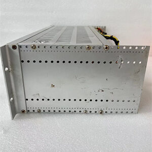
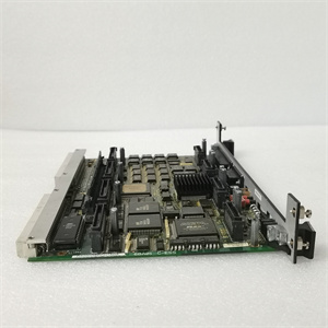
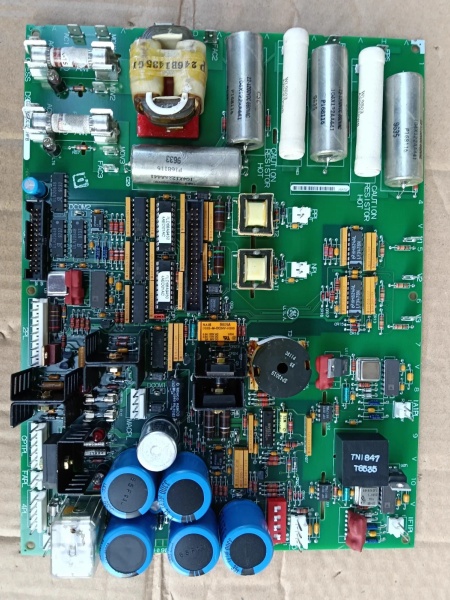
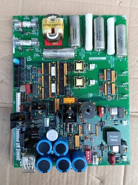
The GE DS200SDCIG2AFB is a DC power supply and instrumentation board within the GE Mark V Series of turbine control systems, designed for Level 2 (Control) of the Purdue Model in industrial automation. It resides in the turbine control cabinet (mounted via DIN rail or panel) and serves as the bridge between:
-
DC2000 Drive Systems: Receives high-voltage AC input (up to 600 V AC) from the drive system.
-
Control Circuits: Transmits regulated 24 V DC power to Mark V main processor boards (e.g., TCTG for generator control, TCCB for trip logic) and field devices (e.g., sensors, actuators).
Upstream Communication
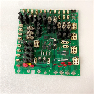
Receives high-voltage AC signals from the DC2000 drive system. The board uses rectifier circuits (diodes) to convert AC to DC and filter circuits (capacitors) to smooth the DC voltage, ensuring stable power output.
Downstream Communication
Transmits regulated DC power to control circuits and field devices. The board also includes signal conditioning circuits (amplifiers, filters) to clean and normalize signals from field devices, ensuring they are compatible with the Mark V controller’s input requirements.
Operational Advantages
-
Stable Power Delivery: The board’s filtering and regulation circuits ensure consistent 24 V DC power, critical for sensitive control circuits and drive systems.
-
Fault Protection: Built-in fuses (with LED indicators) prevent overcurrent damage to the board and downstream components, reducing downtime.
-
Modular Design: Plug-in design allows for quick replacement (≤30 minutes) without shutting down the turbine, minimizing maintenance costs.

DS200SDCIG2AFB
Core Technical Specifications
|
Attribute
|
Specification
|
|---|---|
|
Product Type
|
DC Power Supply & Instrumentation Board
|
|
Part Number
|
DS200SDCIG2AFB
|
|
System Platform
|
GE Mark V Series Turbine Control Systems
|
|
Input Voltage
|
Up to 600 V AC (compatible with DC2000 drivers)
|
|
Output Voltage
|
24 V DC (nominal)
|
|
Operating Temperature
|
-10°C to +55°C (14°F to 131°F)
|
|
Storage Temperature
|
-40°C to +85°C (-40°F to 185°F)
|
|
Humidity
|
5–95% non-condensing
|
|
Dimensions (W×H×D)
|
~120 mm × 150 mm × 20 mm (4.7 in × 5.9 in × 0.8 in) (approximate)
|
|
Weight
|
~0.14 kg (0.31 lbs)
|
|
Certifications
|
CE (European compliance)
|
Customer Value & Operational Benefits
Enhanced Turbine Reliability
The DS200SDCIG2AFB’s stable power delivery and fault protection reduce the risk of turbine misoperation due to power fluctuations. A power plant using the board reported a 99.9% success rate in turbine startups, compared to 95% with traditional power supplies.
Reduced Maintenance Costs
The board’s modular design allows technicians to replace it in minutes without shutting down the turbine. A chemical plant using the DS200SDCIG2AFB cut maintenance downtime by 40% compared to traditional non-modular power supplies.
Cost-Effective Integration
Compatible with GE Mark V Series and existing DC2000 drive systems, the DS200SDCIG2AFB eliminates the need for custom power solutions. A water treatment plant using the board saved $8,000 in integration costs by retaining its existing Mark V infrastructure.
Improved Safety
The board’s fuse protection and CE certification ensure safe operation in hazardous locations (e.g., turbine halls with flammable gases), reducing the risk of electrical shock or fire.
Field Engineer’s Notes (From the Trenches)
When installing the DS200SDCIG2AFB, always verify the input voltage—the board requires a stable 600 V AC input (±10%). I once saw a site where a technician connected a 480 V AC supply to a 600 V AC board, resulting in a burnt-out rectifier circuit. Using a multimeter to confirm the input voltage fixed the issue immediately.Another gotcha: check the fuse status—the board has multiple fuses (with LED indicators) for overcurrent protection. If a fuse blows, the LED will illuminate, indicating a fault. Replace the fuse with a 5A slow-blow fuse (matching the board’s specifications) to resolve the issue.If the board’s output voltage is unstable, check the filter capacitors—the most common cause is a faulty capacitor (use a multimeter to test the capacitance). Replace the capacitor if it is out of specification.DS200SDCIG2AFB
Real-World Applications
-
Power Generation:A coal-fired power plant uses the DS200SDCIG2AFB to power its Mark V turbine control system. The board’s stable power delivery ensures that the turbine’s speed and temperature are controlled accurately, maintaining optimal efficiency.
-
Industrial Manufacturing:A steel mill uses the DS200SDCIG2AFB to power its DC2000 drive systems for rolling mill motors. The board’s fault protection prevents damage to the drive systems, reducing maintenance costs.
-
Oil & Gas:An offshore oil platform uses the DS200SDCIG2AFB to power its Mark V control system. The board’s wide operating temperature range (-10°C to +55°C) withstands the harsh offshore environment, ensuring reliable operation.
High-Frequency Troubleshooting FAQ
Q: What does the “FAULT” LED indicate on the GE DS200SDCIG2AFB?
A: The red “FAULT” LED indicates a critical error, such as:
-
Overcurrent: The output current exceeds the set limit (check the load for shorts);
-
Overvoltage: The input voltage is outside the 600 V AC range (use a multimeter to test the input);
-
Fuse Blown: A fuse has blown (replace the fuse with a 5A slow-blow fuse).
Q: Can the DS200SDCIG2AFB be used with non-GE drive systems?
A: No, the DS200SDCIG2AFB is designed exclusively for GE Mark V Series and DC2000 drive systems. Non-GE drive systems may not provide the correct input voltage or communication signals, leading to board failure.
Q: How do I test the DS200SDCIG2AFB?
A: Use a multimeter to test the following:
-
Input Voltage: Check the voltage at the input terminals (should be 600 V AC ±10%);
-
Output Voltage: Check the voltage at the output terminals (should be 24 V DC ±10%);
-
Fuse Continuity: Test the continuity of each fuse (should be closed).
Q: Why is the DS200SDCIG2AFB’s output voltage unstable?
A: Check three things first:
-
Input Voltage: Ensure the input voltage is stable (use a multimeter to test);
-
Filter Capacitors: Check the filter capacitors for damage (use a multimeter to test the capacitance);
-
Load: Ensure the load is not drawing more current than the board’s rated capacity.
Commercial Availability & Pricing
Please note: The listed price is not the actual final price. It is for reference only and is subject to appropriate negotiation based on current market conditions, quantity, and availability.