Description
System Architecture & Operational Principle
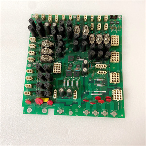
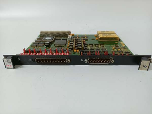
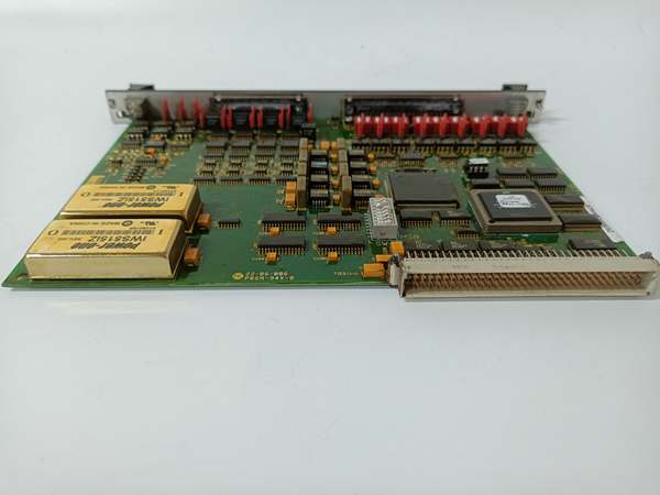
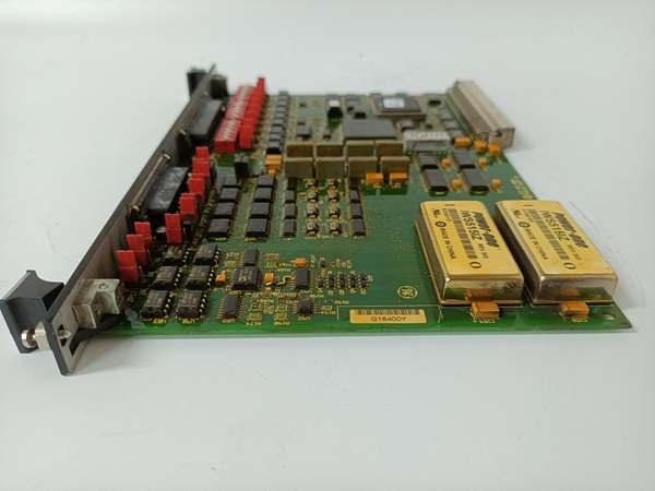
The GE DS200SIOBH1ACA is a VME bus I/O control board sitting at Level 2 (Control) in the Purdue Model. It mounts in a VME rack within the turbine control cabinet, drawing power from the backplane. Upstream, it receives command signals from the Mark V/VI main processor (e.g., TCTG, TCCB) via the VME backplane—these are low-voltage digital words that dictate output states or request input data. Downstream, the board translates these commands into physical signals: it sends 24V DC digital outputs to solenoids and contactors, and reads 4–20mA analog inputs from pressure and temperature transmitters.
Its key advantage lies in the VME backplane architecture, which offers deterministic timing and hot-swappable module replacement—critical for minimizing turbine trip time. The board’s galvanic isolation between the backplane and field side prevents ground loops from damaging sensitive input stages, a common issue in industrial environments.
Core Technical Specifications
-
Bus Interface: VME P1 connector (full-size slot)
-
Signal Types: 24V DC digital I/O, 4–20mA analog inputs
-
Channel Density: 16–32 digital input channels (configurable via jumpers)
-
Communication Bus: VMEbus (A24/D16 addressing)
-
Power Supply: 5V DC from VME backplane
-
Operating Temperature: -40°C to +85°C (-40°F to 185°F)
-
Storage Temperature: -55°C to +125°C (-67°F to 257°F)
-
Humidity: 5–95% non-condensing
-
Dimensions: ~233mm x 160mm (VME single slot)
-
Weight: ~0.45 kg (1 lb)

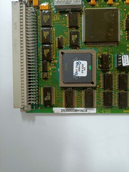
DS200SIOBH1ACA
Customer Value & Operational Benefits
Reduced Cabinet Footprint
By using the VME backplane for power and data, the DS200SIOBH1ACA eliminates the need for separate power supplies and terminal blocks for each signal group. This saves valuable space in crowded turbine control cabinets—critical for retrofits or expansions.
Faster Troubleshooting
The board’s dedicated LED status indicator and predictable jumper map allow technicians to isolate faults to the I/O board itself, rather than chasing wiring issues. This cuts mean-time-to-repair (MTTR) during forced outages—something every plant manager values.
Legacy System Stability
For plants running Mark V/VI systems, this board provides a stable, well-understood interface. Its behavior is documented in decades of operational experience, reducing the risk of unexpected faults during minor control logic changes.
Field Engineer’s Notes (From the Trenches)
When swapping a DS200SIOBH1ACA, document the jumper map first. I’ve seen techs skip this, assuming the new board is pre-configured. The jumpers aren’t standardized—they set everything from input attenuation to fail-safe modes. I once caused a 4–20mA loop to saturate by moving a jumper from 250Ω to 500Ω termination. Also, use a VME extraction tool—the board’s edge connectors are fragile. I had to repair a rack slot where a tech pried the board out with a screwdriver, bending the pins. Finally, check the DIP switches with a multimeter—they can corrode, leading to intermittent opens. A quick continuity check before install saves a future headache.
Real-World Applications
-
Steam Turbine Governor ControlThe board reads speed reference signals from the governor and outputs actuator commands to the hydraulic servomotor. Its analog inputs take feedback from LVDTs on the steam valve position, ensuring precise speed control.
-
Gas Turbine Fuel Skid InterlocksDigital inputs monitor permissives like purge air pressure and bearing oil temperature. If a permissive is lost, the board de-energizes fuel valve solenoids via a dry contact output, initiating a safe shutdown—critical for preventing turbine damage.
DS200SIOBH1ACA
High-Frequency Troubleshooting FAQ
Q: What are the common causes for a “no communication” fault on the DS200SIOBH1ACA?
A: Three primary culprits. First, a backplane power failure—check the 5V DC supply at the VME P1 connector with a multimeter. Second, a bent pin on the VME connector—inspect visually or with a loop. Third, a firmware mismatch if the board was replaced; the EPROM must match the original configuration.
Q: How do I migrate from a DS200SIOBH1ACA to a modern equivalent?
A: The migration isn’t a direct drop-in. Newer boards use different bus protocols (e.g., Ethernet-based I/O). You’ll need to rewire field terminations to the new connector and re-map the I/O in the Mark V/VI software. Budget 4–6 hours for a single board swap including testing.
Q: My analog input readings are noisy—what’s the fix?
A: Start with the basics. Check the shield drain wire on the analog cable—it must be grounded at the board end only. Next, verify the jumper for that channel is set to the correct attenuation (e.g., 1:1 for 0–10V, 1:5 for 0–50V). If that fails, the input op-amp on the board may be degraded—replace the board.
Q: Can I use a DS200SIOBH1ACA in a Mark VIe system?
A: No. The Mark VIe uses a different backplane architecture (e.g., Profibus or Ethernet-based I/O). The DS200SIOBH1ACA is electrically and mechanically incompatible—attempting to force it can damage both the board and the rack.
Please note: The listed price is not the actual final price. It is for reference only and is subject to appropriate negotiation based on current market conditions, quantity, and availability.