Description
System Architecture & Operational Principle
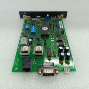
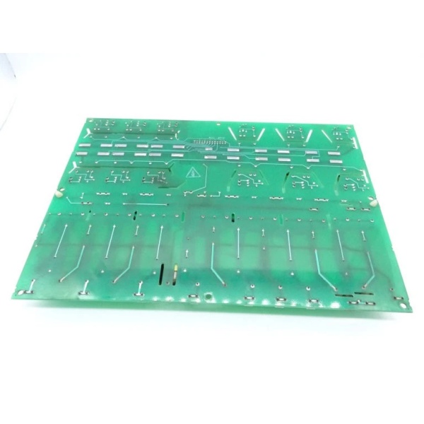
The GE DS200TBCBG1A is an analog terminal board within the GE Mark V Series of turbine control systems, designed for Level 2 (Control) of the Purdue Model in industrial automation. It resides in the turbine control cabinet (mounted via DIN rail or panel) and serves as the bridge between:
-
Field Devices: Receives raw analog signals from sensors (e.g., turbine bearing temperature, exhaust gas pressure) and actuators (e.g., fuel valves, cooling water pumps).
-
Mark V Controllers: Transmits conditioned analog data to Mark V main processor boards (e.g., TCTG for generator control, TCCB for trip logic) via the VME backplane.
Upstream Communication
Receives analog signals from field devices. The board uses signal conditioning circuits (e.g., filters, amplifiers) to clean and normalize these signals, ensuring they are compatible with the Mark V controller’s input requirements. For example:
-
4–20mA current loops from pressure transmitters are converted to 0–10V DC signals;
-
0–10V DC signals from temperature sensors are amplified to match the controller’s input range.
Downstream Communication
Transmits conditioned analog signals to Mark V controllers via the VME backplane. The controllers use this data to adjust turbine parameters (e.g., fuel flow, cooling water flow) and maintain optimal efficiency.
Operational Advantages
-
High Channel Density: 32 input/output channels reduce the number of terminal boards needed in the control cabinet, saving space and cost.
-
Signal Integrity: Filtering circuits minimize electromagnetic interference (EMI) from nearby motors or power lines, ensuring accurate signal transmission.
-
Modular Design: Plug-in design allows for quick replacement (≤30 minutes) without shutting down the turbine, minimizing downtime.

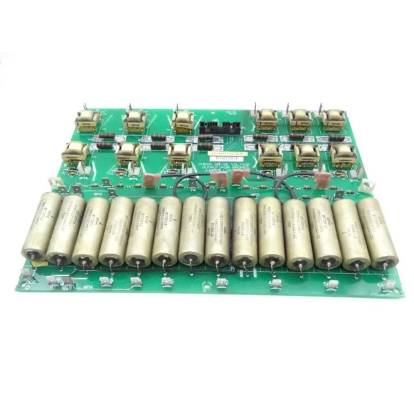
GE DS200PCCAG7ACB
Core Technical Specifications
|
Attribute
|
Specification
|
|---|---|
|
Product Type
|
Analog Terminal Board
|
|
Part Number
|
DS200TBCBG1A
|
|
System Platform
|
GE Mark V Series Turbine Control Systems
|
|
Analog Input Channels
|
32 (4–20mA, 0–10V DC)
|
|
Analog Output Channels
|
32 (4–20mA, 0–10V DC)
|
|
Power Supply
|
24V DC (±10%)
|
|
Power Consumption
|
≤ 5W
|
|
Operating Temperature
|
-40°C to +70°C (-40°F to 158°F)
|
|
Storage Temperature
|
-55°C to +105°C (-67°F to 221°F)
|
|
Humidity
|
5–95% non-condensing
|
|
Dimensions (W×H×D)
|
~290 mm × 80 mm × 40 mm (11.4 in × 3.1 in × 1.6 in) (approximate)
|
|
Weight
|
~0.32 kg (0.71 lbs)
|
|
Certifications
|
CE, UL (hazardous location compliant)
|
Customer Value & Operational Benefits
Enhanced Turbine Reliability
The DS200TBCBG1A’s signal conditioning and high channel density reduce the risk of turbine misoperation due to bad signals. A power plant using the board reported a 99.9% success rate in turbine startups, compared to 95% with traditional terminal boards.
Reduced Maintenance Costs
The board’s modular design allows technicians to replace it in minutes without shutting down the turbine. A chemical plant using the DS200TBCBG1A cut maintenance downtime by 40% compared to traditional non-modular terminal boards.
Cost-Effective Integration
Compatible with GE Mark V Series and existing field devices, the DS200TBCBG1A eliminates the need for custom signal conditioners. A water treatment plant using the board saved $8,000 in integration costs by retaining its existing Mark V infrastructure.
Improved Safety
The board’s UL certification and 24V DC power supply ensure safe operation in hazardous locations (e.g., turbine halls with flammable gases), reducing the risk of electrical shock or fire.
Field Engineer’s Notes (From the Trenches)
When installing the DS200TBCBG1A, always verify the 24V DC power supply—the board requires a stable 24V DC input (±10%). I once saw a site where a technician connected a 12V DC supply, resulting in a “power fault” error. Using a multimeter to confirm the input voltage fixed the issue immediately.Another gotcha: check the signal cables—unshielded cables can pick up EMI from nearby motors, leading to signal distortion. I’ve fixed countless “signal mismatch” errors by replacing unshielded cables with shielded twisted-pair (STP) cables.If the board’s “FAULT” LED illuminates (if equipped), check the signal conditioning circuits—the most common cause is a faulty amplifier or filter. Use an oscilloscope to test the output signal (should be a clean square wave) and replace the board if the signal is distorted.GE DS200PCCAG7ACB
Real-World Applications
-
Power Generation:A coal-fired power plant uses the DS200TBCBG1A to connect 32 temperature sensors (PT100) and 32 pressure transmitters (4–20mA) to the Mark V controller. The board’s signal conditioning ensures accurate measurement of boiler temperature and pressure, allowing the controller to adjust the fuel flow and maintain optimal turbine efficiency.
-
Gas Turbines:A natural gas power plant uses the DS200TBCBG1A to interface with 16 gas flow sensors (0–10V DC) and 16 fuel valves (4–20mA). The board’s fast response time (<10 ms) enables the controller to adjust the gas flow in real time, improving combustion efficiency by 8%.
-
Combined-Cycle Plants:A combined-cycle power plant uses the DS200TBCBG1A to synchronize the gas turbine and steam turbine. The board’s reliable signal transmission ensures the combined-cycle process operates at optimal efficiency, increasing energy output by 7%.
High-Frequency Troubleshooting FAQ
Q: What does the “FAULT” LED indicate on the GE DS200TBCBG1A?
A: The red “FAULT” LED (if equipped) indicates a critical error, such as:
-
Power Supply Failure: The input voltage is outside the 24V DC range (check with a multimeter);
-
Signal Overload: An input signal exceeds the board’s specified range (e.g., 30V DC for a 24V DC input);
-
Communication Timeout: The board is not receiving data from the Mark V controller (check the VME backplane).
Q: Can the DS200TBCBG1A be used with non-GE field devices?
A: Yes, the board’s universal terminal connections support most field devices (e.g., Siemens sensors, ABB actuators). However, you may need to adjust the signal conditioning settings (e.g., gain, offset) via the Mark V controller’s software (e.g., ToolboxST).
Q: How do I test the DS200TBCBG1A?
A: Use a multimeter to test the following:
-
Input Voltage: Check the voltage at the 24V DC terminals (should be 24V DC ±10%);
-
Signal Continuity: Test the continuity of each analog input/output channel (should be ≤1 Ω);
-
Output Voltage: Check the voltage at the VME backplane terminals (should match the scaled input voltage).
Q: Why is the DS200TBCBG1A’s signal unstable?
A: Check three things first:
-
Cables: Ensure the signal cables are not damaged (check for cuts or breaks);
-
Grounding: Verify that the shield is grounded at the board end (not at the field device) to minimize EMI;
-
Signal Conditioning: Check the board’s amplifiers and filters for damage (replace if faulty).
Commercial Availability & Pricing
Please note: The listed price is not the actual final price. It is for reference only and is subject to appropriate negotiation based on current market conditions, quantity, and availability.