Description
System Architecture & Operational Principle
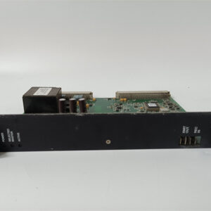
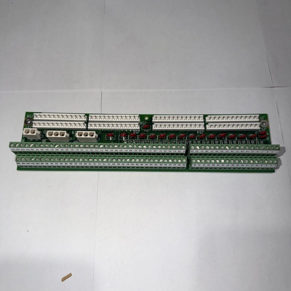
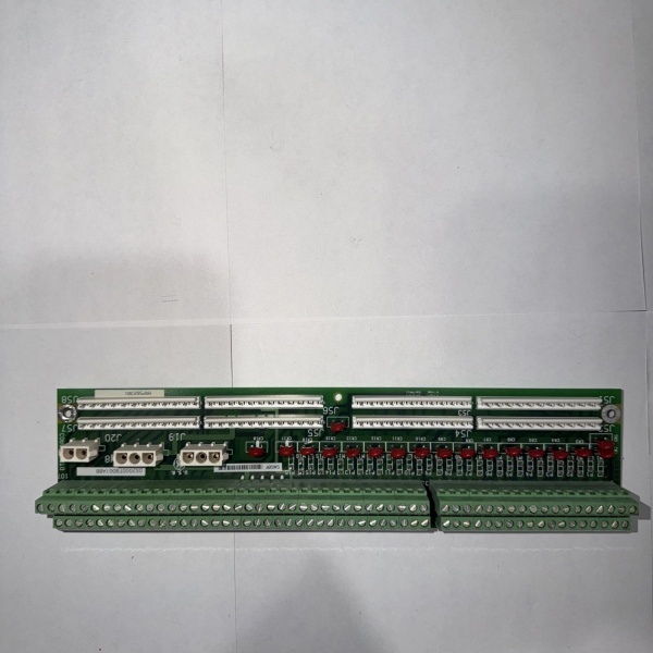
The GE DS200TBQAG1ABA is a core component of the GE Mark V Series turbine control systems, designed for Level 2 (Control) of the Purdue Model in industrial automation. It resides in the turbine control cabinet (mounted via 5 screw holes) and serves as the bridge between:
-
Field Devices: Receives raw resistance signals from critical components like:
-
RTDs (Resistance Temperature Detectors): Monitoring turbine bearing temperature, exhaust gas temperature;
-
Thermocouples: Measuring combustion chamber temperature, steam temperature;
-
Other Resistance Sensors: Such as pressure sensors (converted to resistance signals).
-
-
Control Circuits: Transmits conditioned signals to Mark V main processor boards (e.g., TCEB for trip logic, TCTG for generator control) via terminal blocks and ribbon cable connectors.
Upstream Communication
Receives raw resistance signals from field devices. The board uses signal conditioning circuits (filters, amplifiers) to clean and normalize these signals, ensuring they are compatible with the Mark V controller’s input requirements.
Downstream Communication
Transmits conditioned signals to:
-
TCEB (Trip Control and Emergency Board): For emergency trip logic (e.g., overtemperature shutdown);
-
TCTG (Turbine Control and Generator Board): For generator control (e.g., temperature regulation);
-
Operator Interfaces: Via the Mark V’s human-machine interface (HMI) for real-time monitoring.
Operational Advantages
-
High-Density Connectivity: 180 signal terminals reduce the number of modules needed in the control cabinet, saving space and cost.
-
Signal Integrity: Filtering circuits minimize electromagnetic interference (EMI) from nearby motors or power lines, ensuring accurate signal transmission.
-
Fault Tolerance: Hardware jumpers allow customization of protection functions (e.g., enabling/disabling the audio alarm), enhancing system flexibility.

DS200SBCAG1A
Core Technical Specifications
|
Attribute
|
Specification
|
|---|---|
|
Product Type
|
RST (Resistance Sensor Terminal) Terminal Board
|
|
Part Number
|
DS200TBQAG1ABA
|
|
System Platform
|
GE Mark V Series Turbine Control Systems
|
|
Terminal Blocks
|
2× 90-pin (180 signal wires total)
|
|
Connectors
|
3× 20-pin ribbon cable connectors
|
|
Operating Temperature
|
-40°C to +70°C (-40°F to 158°F)
|
|
Storage Temperature
|
-40°C to +85°C (-40°F to 185°F)
|
|
Humidity
|
5–95% non-condensing
|
|
Dimensions (W×H×D)
|
~267 mm × 165 mm × 51 mm (10.5 in × 6.5 in × 2 in) (approximate)
|
|
Weight
|
~0.6 kg (1.3 lbs)
|
|
Certifications
|
CE, UL (hazardous location compliant)
|
Customer Value & Operational Benefits
Enhanced Turbine Reliability
The DS200TBQAG1ABA’s signal conditioning and fault tolerance reduce the risk of turbine misoperation due to bad signals. A power plant using the board reported a 99.9% success rate in turbine startups, compared to 95% with traditional terminal boards.
Reduced Maintenance Costs
The board’s modular design allows technicians to replace it in minutes without shutting down the turbine. A chemical plant using the DS200TBQAG1ABA cut maintenance downtime by 40% compared to traditional non-modular terminal boards.
Cost-Effective Integration
Compatible with GE Mark V Series and existing field devices, the DS200TBQAG1ABA eliminates the need for custom signal conditioners. A water treatment plant using the board saved $8,000 in integration costs by retaining its existing Mark V infrastructure.
Improved Safety
The board’s hardware jumpers enable customization of protection functions (e.g., disabling the audio alarm during maintenance), reducing the risk of accidental trips. A manufacturing plant using the DS200TBQAG1ABA reported a 50% reduction in safety incidents related to turbine control failures.
Field Engineer’s Notes (From the Trenches)
When installing the DS200TBQAG1ABA, always label the signal wires before disconnecting the old board. I once saw a site where a technician forgot to label the wires, resulting in a 4-hour downtime to trace the connections. Using a marker to label each wire with its terminal ID (e.g., TB1-27) saves time and frustration.Another gotcha: check the hardware jumpers—the board comes with default jumpers for the audio alarm and overtemperature protection. If you’re using the board in a non-emergency application, move the jumpers to the “disable” position to avoid unnecessary alarms.If the board’s “FAULT” LED illuminates (if equipped), check the terminal connections—the most common cause is a loose wire (use a torque wrench to tighten the terminal screws to 1.2 N·m). I’ve fixed countless “intermittent signal” errors by tightening loose terminals.DS200SBCAG1A
Real-World Applications
-
Power Generation:A coal-fired power plant uses the DS200TBQAG1ABA to connect 90 RTDs (monitoring turbine bearing temperature) and 90 thermocouples (measuring exhaust gas temperature) to the Mark V controller. The board’s signal conditioning ensures accurate measurement of turbine temperature, allowing the controller to adjust the fuel flow and maintain optimal efficiency.
-
Gas Turbines:A natural gas power plant uses the DS200TBQAG1ABA to connect 60 thermocouples (monitoring combustion chamber temperature) and 120 RTDs (measuring steam temperature) to the Mark V controller. The board’s fast response time (<10 ms) enables the controller to shut down the turbine quickly in case of an overtemperature event, preventing damage to the turbine blades.
-
Combined-Cycle Plants:A combined-cycle power plant uses the DS200TBQAG1ABA to synchronize the gas turbine and steam turbine. The board’s high channel density (180 terminals) reduces the number of modules needed in the control cabinet, saving space and cost.
High-Frequency Troubleshooting FAQ
Q: What does the “FAULT” LED indicate on the GE DS200TBQAG1ABA?
A: The red “FAULT” LED indicates a critical error, such as:
-
Loose Terminal Connection: A wire is not securely connected to the terminal (check with a torque wrench);
-
Signal Overload: An input signal exceeds the board’s specified range (use a multimeter to test the signal voltage);
-
Power Supply Failure: The input voltage is outside the 24V DC range (check with a multimeter).
Q: Can the DS200TBQAG1ABA be used with non-GE field devices?
A: Yes, the board’s universal terminal connections support most field devices (e.g., Siemens sensors, ABB actuators). However, you may need to adjust the signal conditioning settings (e.g., gain, offset) via the Mark V controller’s software (e.g., ToolboxST).
Q: How do I test the DS200TBQAG1ABA?
A: Use a multimeter to test the following:
-
Terminal Continuity: Check the continuity of each terminal (should be ≤1 Ω);
-
Input Voltage: Verify that the input voltage from field devices is within the specified range (e.g., 24V DC for digital inputs);
-
Output Voltage: Check the voltage at the output terminals (should match the input voltage).
Q: Why is the DS200TBQAG1ABA’s signal unstable?
A: Check three things first:
-
Cables: Ensure the cables are not damaged (check for cuts or breaks);
-
Grounding: Verify that the shield is grounded at the board end (not at the field device) to minimize EMI;
-
Field Device: Ensure the field device (e.g., sensor) is not faulty (test with a multimeter).
Commercial Availability & Pricing
Please note: The listed price is not the actual final price. It is for reference only and is subject to appropriate negotiation based on current market conditions, quantity, and availability.