Description
System Architecture & Operational Principle
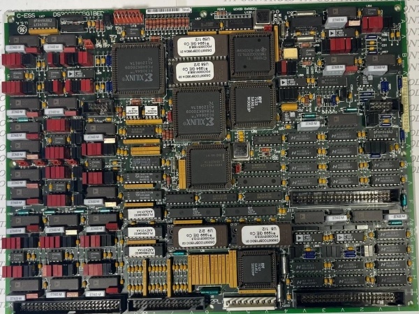
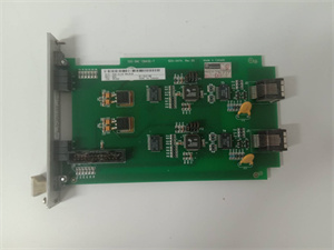
GE DS200TCCBG1B
Core Technical Specifications
- Physical Interface: Dual 50‑pin IDC connectors (JCC, JDD) for field wiring; standard Mark V PCB form factor (9.2 × 6.3 in)
- Signal Types: 4–20 mA, 0–1 mA, RTD (Pt100/Pt1000), low‑voltage analog inputs
- Channel Density: Configurable multi‑channel analog input (dependent on jumper/termination board)
- Resolution: 12‑bit A/D conversion (including sign bit)
- Communication Bus: Mark V proprietary parallel backplane
- Environmental Tolerance: Operating temp −30°C to +65°C; 5–95% RH (non‑condensing)
- Power Draw: Typical 150 mA @ 5 VDC (backplane‑powered)
- Isolation: Channel‑to‑backplane functional isolation (707 VDC test)
- Processing: Onboard Intel 80196 microcontroller
- Memory: Multiple PROM modules for firmware/calibration storage
- Diagnostics: 1 front‑side LED for run/fault status; jumper‑configurable signal routing (JP1/JP2/JP3)
- Weight: 0.6 kg
Customer Value & Operational Benefits
The DS200TCCBG1B’s galvanic isolation and onboard signal processing eliminate ground loops and noise-induced measurement errors, preventing false trips on critical analog parameters (e.g., bearing temperature, compressor pressure). Accurate, stable analog inputs directly reduce nuisance shutdowns in gas and steam turbine applications, boosting unit availability by minimizing unplanned downtime.
Local signal conditioning and 12‑bit resolution deliver high‑fidelity process data to the Mark V controller, enabling precise Sequence of Events (SOE) recording during transients. The single LED status indicator provides immediate visual fault confirmation, while jumper‑configurable inputs simplify field troubleshooting. These features cut mean time to repair (MTTR) for analog I/O issues by up to 40% compared to non‑intelligent I/O boards.
As a mature, field‑proven component of the Mark V platform, the DS200TCCBG1B offers full backward compatibility with earlier TCCB revisions (e.g., DS200TCCBG1A). Its robust hardware design and readily available replacement stock ensure long‑term support for legacy Mark V systems, eliminating costly early forklift upgrades and extending asset life by 10+ years.
GE DS200TCCBG1B
Field Engineer’s Notes (From the Trenches)
When installing or replacing a DS200TCCBG1B in a Mark V cabinet, never power up the board before verifying jumper settings (JP1/JP2/JP3) and securing the 50‑pin ribbon cables to JCC/JDD. Misconfigured jumpers can cause signal scaling errors or full‑channel failure, while loose ribbon cables often lead to intermittent analog faults that are extremely hard to trace. Always use the factory‑supplied termination board (e.g., DS200TBCBG1A) with this module—direct field wiring to the JCC/JDD connectors without the termination board risks backplane damage from induced voltage transients. Also, note that this board draws a non‑trivial 150 mA from the 5 V backplane rail; in densely populated R5 cabinets, verify total backplane power budget to avoid undervoltage faults during hot‑swap operations. Finally, when replacing an older TCCB board, upload the existing calibration constants from the PROMs before removing the old unit—manual re‑calibration of RTD and 4–20 mA channels is time‑consuming and prone to error.
Real-World Applications
- Gas Turbine Bearing & Vibration Monitoring
The DS200TCCBG1B acquires high‑resolution analog signals from RTDs (bearing temperature) and 4–20 mA vibration transmitters. It conditions and digitizes these signals, sending real‑time data to the Mark V controller for overspeed protection, vibration alarm logic, and performance trending. Its isolation prevents ground loops between field sensors and the control cabinet, ensuring accurate, reliable measurements in high‑EMI turbine skid environments.
- Steam Turbine Steam Flow & Pressure Control
In combined‑cycle power plants, this module interfaces with differential pressure flow transmitters and analog pressure sensors to measure main steam flow, inlet pressure, and exhaust conditions. The onboard microprocessor linearizes the raw sensor signals, providing the Mark V with precise process data for steam valve positioning and load‑following control. Fast backplane data transfer ensures tight closed‑loop response during load ramps and grid frequency disturbances.
High-Frequency Troubleshooting FAQ
A: Yes, the DS200TCCBG1B is fully backward‑compatible with the DS200TCCBG1A and other earlier TCCB revisions. It uses the same backplane interface, pinout, and firmware structure. When replacing a 1A with a 1B, verify jumper settings match the original configuration; no software changes are required for basic operation.
A: A dark LED typically signals no 5 VDC backplane power or a critical onboard fault. First, check the cabinet’s backplane power supply and ensure the board is fully seated in the R5 rack. If power is present, inspect the 50‑pin JCC/JDD connectors for bent pins or loose cables. A faulty onboard Intel 80196 microprocessor or PROM module will also extinguish the LED; in this case, the board requires repair or replacement.
A: Jumper configuration is signal‑type specific. For RTD inputs (Pt100), set JP1 to the 2‑ or 3‑wire RTD position, JP2 for excitation current, and JP3 for cold‑junction compensation. For 4–20 mA inputs, place all jumpers in the “current loop” positions. Always cross‑reference the jumper map printed on the board’s PCB with the Mark V installation manual—incorrect settings will result in saturated or zero readings.
A: Common causes include inadequate field wiring shielding, ground loops, or loose termination board connections. Use twisted‑pair, shielded cable for all analog runs, and ground the shield at the control cabinet end only. Ensure the termination board (e.g., DS200TBCBG1A) is securely mounted and all field wires are torqued to specification. Verify that the board’s galvanic isolation is intact—failed isolation will introduce common‑mode noise into the measurement circuit.