Description
System Architecture & Operational Principle
Core Technical Specifications
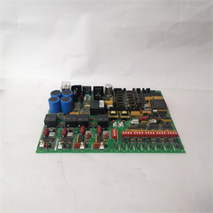
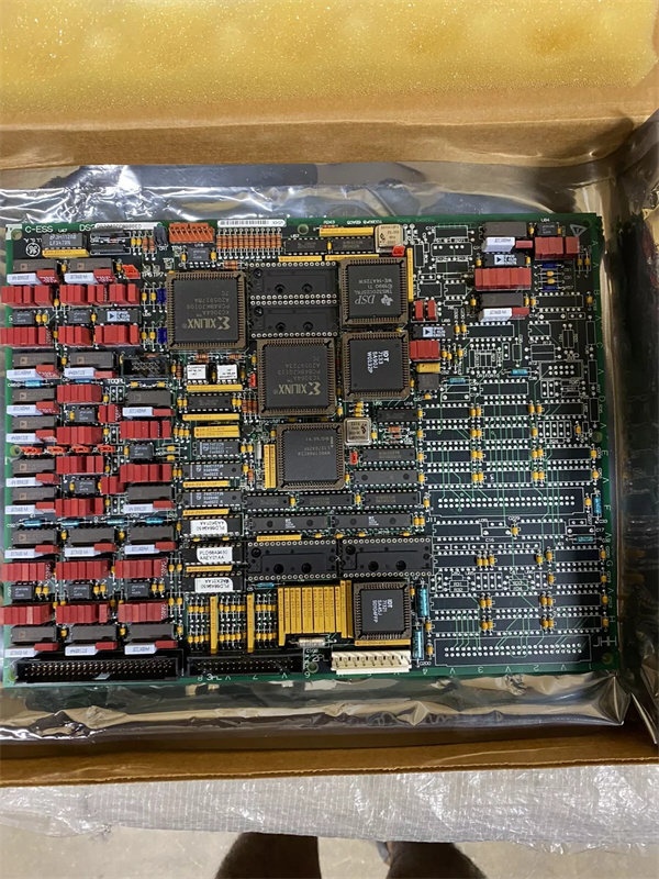
- Physical Interface: Dual 50‑pin IDC connectors (JCC, JDD); 3PL COREBUS connector; standard Mark V PCB form factor
- Signal Types: 4–20 mA, 0–1 mA, RTD (Pt100/Pt1000), generator/bus voltage, line current inputs
- Processing: Intel 80196 16‑bit microcontroller
- Memory: 2 × programmable EEPROMs (configuration/calibration storage)
- Communication: Mark V proprietary COREBUS (3PL connector)
- Environmental: Operating temp −30°C to +65°C; 5–95% RH (non‑condensing)
- Power: Backplane‑powered (5 VDC typical); no external field power required
- Isolation: Channel‑to‑backplane functional isolation
- Diagnostics: 1 front‑side LED (run/fault status); jumpers J1–J5, J14 for configuration
- Weight: 2 lbs (0.9 kg)
- Manual Reference: GEH‑6153
GE DS200TCCBG8B
Customer Value & Operational Benefits
The DS200TCCBG8B’s dedicated signal conditioning and galvanic isolation eliminate ground loops and EMI‑induced measurement errors on critical analog parameters (e.g., bearing temp, generator voltage). Accurate, stable inputs directly reduce false turbine trips, boosting unit availability and reducing unplanned downtime in gas/steam turbine applications.
Onboard processing and high‑resolution signal digitization deliver precise data for SOE recording during transients. A single LED provides immediate fault indication, while configurable jumpers (J1–J5) simplify field diagnostics. These features cut mean time to repair (MTTR) for analog I/O issues by up to 40% compared to non‑intelligent I/O boards.
As a mature Mark V component, the DS200TCCBG8B offers full backward compatibility with earlier TCCB revisions. Its robust design and readily available replacement stock extend the life of legacy Mark V systems, eliminating costly forklift upgrades and ensuring long‑term support for aging turbine control assets.
Field Engineer’s Notes (From the Trenches)
When replacing a DS200TCCBG8B in an R5 cabinet, always document the existing jumper settings (J1–J5, J14) and ribbon cable connections (JCC/JDD) before removing the old board. Misconfigured jumpers will cause incorrect scaling on generator voltage or line current inputs, while reversed ribbon cables lead to intermittent faults that are hard to trace. This board draws non‑trivial backplane current; verify the total 5 VDC power budget in densely populated cabinets to avoid undervoltage faults during hot‑swap. Never power up the board without the TBCB termination board—direct field wiring to JCC/JDD risks backplane damage from voltage transients. Finally, back up the EEPROM configuration from the old board before replacement; manual re‑calibration of RTD and voltage channels is time‑consuming and error‑prone.
Real-World Applications
- Gas Turbine Generator Voltage & Current Monitoring
The DS200TCCBG8B acquires and conditions generator/bus voltage and line current signals from PT/CTs. It calculates megawatt, power factor, and VARs for power system monitoring, transmitting processed data to the Mark V controller for excitation control and grid synchronization. Isolation protects against high‑voltage transients in generator compartments.
- Steam Turbine Bearing & Process Parameter Control
In combined‑cycle plants, this module interfaces with RTDs (bearing temp) and 4–20 mA transmitters (steam pressure/flow). Onboard scaling converts raw signals to engineering units, providing the Mark V with precise data for steam valve control and performance trending. Fast backplane communication ensures tight closed‑loop response during load changes.
GE DS200TCCBG8B
High-Frequency Troubleshooting FAQ
A: Yes, the DS200TCCBG8B is fully backward‑compatible with earlier TCCB revisions (e.g., 1B, 3B). It uses the same backplane interface, pinout, and firmware structure. When replacing an older board, match jumper settings (J1–J5) to the original configuration; no software changes are required for basic operation.
A: A dark LED signals no 5 VDC backplane power or a critical onboard fault. First, verify the board is fully seated in the R5 rack and check the backplane power supply. If power is present, inspect JCC/JDD for bent pins or loose cables. A faulty 80196 microprocessor or EEPROM will also extinguish the LED; in this case, the board requires repair or replacement.
A: Jumpers J1–J5 configure generator/bus voltage and line current monitoring functions. For standard 4–20 mA/RTD inputs, set these jumpers to the “disabled” position. For generator voltage monitoring, refer to the GEH‑6153 manual for specific jumper positions based on your PT/CT ratios. J14 connects the RS232 port to DCOM for configuration access.
A: Common causes include inadequate shielding, ground loops, or loose termination board connections. Use twisted‑pair, shielded cable for all analog runs, grounding the shield at the control cabinet end only. Ensure the TBCB termination board is securely mounted and all field wires are torqued to specification. Verify channel isolation—failed isolation introduces common‑mode noise into measurements.