Description
System Architecture & Operational Principle
Core Technical Specifications
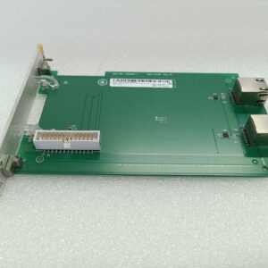
- Physical Interface: Dual 50‑pin IDC connectors (JQ, JR); JO1/JO2 output connectors; JX1/JX2 IONET connectors; JP power connector
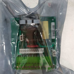
- Signal Type: Dry contact inputs (24 VDC nominal); relay‑drive outputs (non‑isolated)
- Channel Density: Configurable via terminal boards (typically 32 channels: 16 inputs / 16 outputs)
- Communication Bus: Mark V proprietary IONET high‑speed backplane
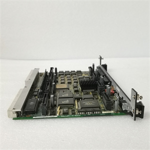
- Processing: Onboard microcontroller with PROM firmware storage
- Isolation: Input‑to‑backplane optical isolation (2500 Vrms test)
- Configuration: 8 jumpers (JP1–JP8) for IONET address, termination, stall timer, test mode
- Diagnostics: 10‑LED array for channel status; 1 system run/fault LED
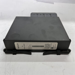
- Environmental: Operating temp 0°C to +70°C; 5–95% RH (non‑condensing); full conformal coating
- Power: Backplane‑powered (5 VDC, 200 mA typical)
- Weight: 1.68 kg
- Manual Reference: GEH‑6153 / Mark V TCDA Board Documentation
- Revision: Functional Rev B, 2nd Rev H, Artwork Rev D
DS200TCDAH1BHD
Customer Value & Operational Benefits
The DS200TCDAH1BHD’s full conformal coating is the key differentiator from standard TCDA boards. It shields the PCB from moisture, salt spray, dust, and industrial chemicals, drastically reducing corrosion and component failure in offshore platforms, coastal power plants, and heavy industrial facilities. This directly extends board life by 30–50% and minimizes unplanned outages due to environmental degradation.
Optical input isolation eliminates ground loops and noise‑induced false triggers on critical safety interlocks (e.g., overspeed, vibration, flame detection). This reduces nuisance turbine trips, boosting unit availability and preventing costly unplanned outages in power generation and industrial turbine applications.
The 10‑LED diagnostic array provides real‑time, channel‑level status visibility, enabling technicians to pinpoint faulty inputs/outputs in seconds. IONET bus communication ensures rapid fault reporting to the main controller, while jumper‑configurable test modes simplify offline diagnostics. These features cut mean time to repair (MTTR) for digital I/O issues by up to 50%.
Field Engineer’s Notes (From the Trenches)
When deploying the DS200TCDAH1BHD in harsh environments, never remove or damage the conformal coating—it’s the board’s primary defense against corrosion. When replacing a non‑coated TCDA board with this HD variant, match all jumper settings (JP1–JP8) exactly, especially IONET address (JP4–JP6) and termination (JP2–JP3). For input wiring, use twisted‑pair, shielded cable and ground the shield at the control cabinet end only to minimize EMI. The HD model’s thicker coating can make connector insertion slightly tighter—use gentle, even pressure to seat JQ/JR and JX1/JX2 fully; forcing connectors can damage pins. Always verify the JP power connector is fully seated before powering up—loose power connections cause intermittent IONET faults that are notoriously difficult to trace. When testing outputs, use the JP8 test jumper to force outputs locally without energizing field devices, preventing accidental actuation of solenoids or relays during maintenance.
Real-World Applications
- Offshore Gas Turbine Safety Interlock Monitoring
The DS200TCDAH1BHD acquires dry contact inputs from safety devices: overspeed switches, vibration probes, flame detectors, and emergency stop (E‑Stop) pushbuttons on offshore platforms. Its conformal coating withstands salt spray and high humidity, ensuring reliable signal detection in harsh marine environments. The board transmits these critical states over IONET to the Mark V controller, which executes safety logic to initiate turbine shutdowns when unsafe conditions are detected.
- Coastal Power Plant Steam Turbine Auxiliary System Control
In coastal combined‑cycle power plants, this module receives status inputs from auxiliary systems (lube oil pressure switches, seal air flow contacts, feed pump run permissives). It outputs control signals to TCRA relay boards, which actuate motor starters for lube oil pumps, seal air fans, and steam drain valves. The conformal coating protects against salt‑laden air, ensuring long‑term reliability in corrosive coastal conditions. Fast IONET communication ensures tight coordination between auxiliary systems and main turbine control logic.
DS200TCDAH1BHD
High-Frequency Troubleshooting FAQ
A: First, check the system LED for a fault indication. Verify the JP power connector is secure and 5 VDC backplane power is present. Inspect JX1/JX2 IONET cables for damage or loose connections. Confirm jumpers JP4–JP6 (IONET address) are set to the factory configuration for the Q11/Q51/Q21 core. A faulty onboard microprocessor or PROM will also cause IONET communication failure; in this case, the board requires repair or replacement. Ensure the conformal coating is intact—damage to the coating near connectors can cause signal issues.
A: Common causes include inadequate input wiring shielding, ground loops, or faulty field devices. Use a multimeter to verify 24 VDC is present at the input terminals. Check for loose connections at the DTBA/DTBB terminal boards. Ensure input signals are dry contacts (no external voltage) and that the optical isolation is intact. EMI from nearby high‑voltage cables can also corrupt inputs—reroute analog/digital wiring away from power cables. Inspect the conformal coating for damage near input connectors, as this can introduce noise.
A: Yes, the DS200TCDAH1BHD is fully backward‑compatible with all earlier TCDA revisions. It uses the same backplane interface, pinout, and firmware structure. When replacing, match the jumper settings (JP1–JP8) from the old board to the new one; no software changes are required for basic operation. The HD variant’s conformal coating provides superior environmental protection, making it the preferred replacement for harsh industrial environments.
A: Install jumper JP8 to enable test mode. In this mode, the board disconnects from the IONET bus and allows local control of output channels via the front‑panel LEDs. Use this to verify output relay drivers and wiring without affecting turbine operation. Always remove JP8 before returning the board to service to restore normal IONET communication. When in test mode, ensure the conformal coating is not damaged during jumper manipulation.