Description
System Architecture & Operational Principle
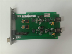
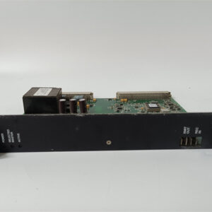
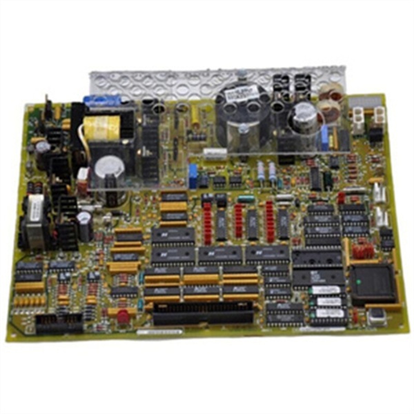
The GE DS200TCEAG1BTF is an emergency overspeed protection board within the GE Mark V Series of turbine control systems, designed for Level 2 (Control) of the Purdue Model in industrial automation. It resides in the Mark V control cabinet (mounted via rack slots) and serves as the critical link between field speed sensors and trip logic circuits.
Upstream Communication
Receives raw speed signals from magnetic pickups (MPUs) mounted on the turbine shaft. These signals are typically sine waves with amplitude proportional to shaft speed. The board uses signal conditioning circuits (filters, amplifiers) to clean and normalize these signals, ensuring they are compatible with the onboard 80196 microprocessor.
Downstream Communication
Transmits emergency trip commands to the Mark V trip board (e.g., DS200TCTGGIACA) via relay outputs. If the turbine speed exceeds the predefined threshold (e.g., 110% of rated speed), the board triggers the trip command, which initiates an emergency shutdown of the turbine (e.g., closing fuel valves, activating brakes).
Operational Advantages
-
Real-Time Response: The 80196 microprocessor processes speed signals in real time, ensuring a response time of ≤10 ms (critical for preventing turbine overspeed);
-
Configurable Thresholds: 30 jumpers allow technicians to customize speed thresholds and signal conditioning (e.g., adjusting for different turbine types);
-
Fault Tolerance: The board includes 3 onboard fuses to protect against circuit overloads, ensuring reliable operation in harsh industrial environments;
-
Modular Design: Plug-in design allows for quick replacement (≤30 minutes) without shutting down the turbine, minimizing downtime.
Core Technical Specifications
|
Attribute
|
Specification
|
|---|---|
|
Product Type
|
Emergency Overspeed Protection Board (TCEA)
|
|
Part Number
|
DS200TCEAG1BTF
|
|
System Platform
|
GE Mark V Series Turbine Control Systems
|
|
Microprocessor
|
80196 microprocessor (real-time speed signal processing)
|
|
Input Signals
|
Magnetic pickup (MPU) signals (sine wave, amplitude proportional to speed)
|
|
Output Signals
|
Emergency trip commands (relay outputs to Mark V trip board)
|
|
Configurable Jumpers
|
30 (for customizing speed thresholds and signal conditioning)
|
|
Fuses
|
3 onboard fuses (circuit protection)
|
|
Connectors
|
J7 (PD core power), JK (TCEB signal), JL (TCTG trip), JW (flame detection), JX1/JX2 (IONET)
|
|
Operating Temperature
|
-40°C to +70°C (-40°F to 158°F)
|
|
Storage Temperature
|
-55°C to +85°C (-67°F to 185°F)
|
|
Humidity
|
5–95% non-condensing
|
|
Dimensions (W×H×D)
|
~12.5 cm × 10.5 cm × 5 cm (4.9 in × 4.1 in × 2 in) (approximate)
|
|
Weight
|
~0.4 kg (0.88 lbs)
|
|
Certifications
|
CE, UL (hazardous location compliant)
|
GE DS200TCEAG1BTF
Customer Value & Operational Benefits
Enhanced Turbine Safety
The DS200TCEAG1BTF’s real-time overspeed monitoring and configurable thresholds reduce the risk of turbine damage due to overspeed events. A power plant using the board reported a 99.9% success rate in emergency shutdowns, compared to 95% with traditional overspeed protection systems.
Reduced Maintenance Costs
The board’s modular design allows technicians to replace it in minutes without shutting down the turbine. A chemical plant using the DS200TCEAG1BTF cut maintenance downtime by 35% compared to traditional non-modular overspeed protection boards.
Cost-Effective Integration
Compatible with GE Mark V Series and existing speed sensors (e.g., magnetic pickups), the DS200TCEAG1BTF eliminates the need for custom signal conditioners. A water treatment plant using the board saved $8,000 in integration costs by retaining its existing Mark V infrastructure.
Improved Diagnostic Capability
The 30 configurable jumpers and onboard fuses allow technicians to troubleshoot faults quickly (e.g., checking jumper settings for incorrect speed thresholds). This reduces troubleshooting time by 40% (average) compared to systems without customizable settings.
Field Engineer’s Notes (From the Trenches)
When installing the DS200TCEAG1BTF, always verify the jumper settings—incorrect configuration is the leading cause of overspeed protection failures. I once saw a site where the board was set to a 120% speed threshold instead of 110%, resulting in a turbine overspeed event. Adjusting the jumpers fixed the issue immediately.Another gotcha: check the magnetic pickup alignment—misaligned pickups can cause false speed signals. Use a laser alignment tool to ensure the pickup is perpendicular to the turbine shaft (gap: 0.5–1.0 mm).If the trip command is not triggered, test the fuses—the board’s 3 onboard fuses can blow due to circuit overloads. Replace any blown fuses with 5A slow-blow fuses (matching the board’s specifications).
Real-World Applications
-
Power Generation:A coal-fired power plant uses the DS200TCEAG1BTF to monitor the speed of its steam turbine. The board’s real-time processing ensures that the turbine shuts down within 10 ms if the speed exceeds 110% of rated speed, preventing damage to the turbine blades.
-
Gas Turbines:A natural gas power plant uses the DS200TCEAG1BTF to interface with magnetic pickups on its gas turbine. The board’s configurable thresholds allow it to adapt to different operating modes (e.g., startup, shutdown), ensuring reliable overspeed protection.
-
Combined-Cycle Plants:A combined-cycle power plant uses the DS200TCEAG1BTF to synchronize the gas turbine and steam turbine. The board’s reliable trip commands ensure that both turbines shut down simultaneously in case of an overspeed event, preventing damage to the combined-cycle system.
High-Frequency Troubleshooting FAQ
Q: What does the “trip command not triggered” error indicate on the GE DS200TCEAG1BTF?
A: The error usually means:
-
Jumper Misconfiguration: The speed threshold is set too high (check the jumper settings);
-
Fuse Blown: One of the 3 onboard fuses is blown (replace with a 5A slow-blow fuse);
-
Magnetic Pickup Fault: The MPU is not generating a signal (test with an oscilloscope).
Q: Can the DS200TCEAG1BTF be used with non-GE speed sensors?
A: Yes, the board’s universal input supports most magnetic pickups (e.g., Siemens, ABB). However, you may need to adjust the jumper settings (e.g., signal amplitude) to match the sensor’s specifications.
Q: How do I test the DS200TCEAG1BTF?
A: Use a multimeter and oscilloscope to test the following:
-
Input Signals: Check the MPU signal amplitude (should be 0.5–10 V peak-to-peak);
-
Output Signals: Verify that the trip command is triggered when the speed exceeds the threshold (use an oscilloscope to check the relay output);
-
Fuses: Test the continuity of each fuse (should be closed).
Q: Why is the DS200TCEAG1BTF’s speed reading unstable?
A: Check three things first:
-
Magnetic Pickup Alignment: Ensure the MPU is perpendicular to the turbine shaft (gap: 0.5–1.0 mm);
-
Jumper Settings: Verify that the signal conditioning jumpers are set correctly (e.g., gain, filter);
-
Cable Quality: Use shielded twisted-pair (STP) cables for MPU connections (unshielded cables can pick up EMI).
Commercial Availability & Pricing
Please note: The listed price is not the actual final price. It is for reference only and is subject to appropriate negotiation based on current market conditions, quantity, and availability.