Description
System Architecture & Operational Principle
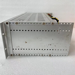
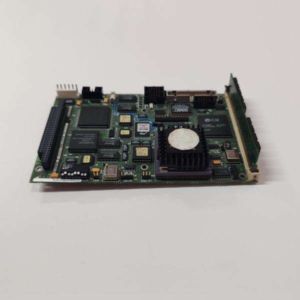
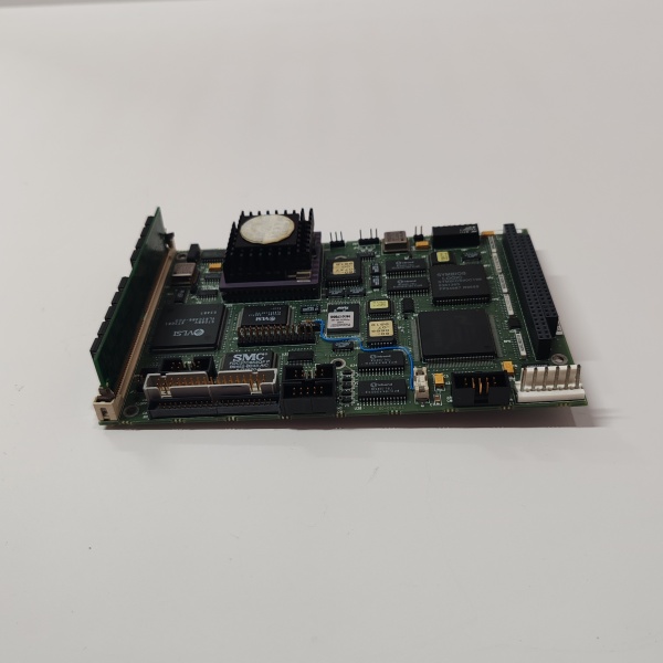
The GE DS200UCPBG6AFB is an I/O Engine CPU Board (UCPB) within the GE Mark V LM Series of turbine control systems, designed for Level 2 (Control) of the Purdue Model in industrial automation. It resides in the turbine control cabinet as a daughterboard mounted on the STCA (System Terminal Control Assembly), which is the core of the Mark V LM system.
Upstream Communication
Receives raw analog/digital signals from field devices (e.g., temperature sensors, pressure transmitters, actuators) via the STCA. These signals are typically 4–20 mA current loops or 0–10 V DC voltage signals, representing parameters like turbine speed, temperature, or pressure.
Downstream Communication
Transmits processed I/O data to other Mark V LM system components (e.g., main processor boards, HMIs) via the COREBUS network, a proprietary GE communication protocol. The COREBUS network enables real-time data exchange between the I/O Engine and other system modules, ensuring coordinated turbine control.
Operational Advantages
-
Integrated I/O Processing: Combines signal processing and data transmission functions, reducing the need for additional modules and simplifying system architecture.
-
Real-Time Performance: The COREBUS network ensures low-latency data transfer, critical for turbine protection and control (e.g., responding to overspeed conditions in milliseconds).
-
Modular Design: As a daughterboard, the DS200UCPBG6AFB can be easily replaced or upgraded without modifying the entire STCA, minimizing downtime during maintenance.

DS200UCPBG6AFB
Core Technical Specifications
|
Attribute
|
Specification
|
|---|---|
|
Product Type
|
I/O Engine CPU Board (UCPB)
|
|
Part Number
|
DS200UCPBG6AFB
|
|
System Platform
|
GE Mark V LM Series Turbine Control Systems
|
|
Power Requirement
|
+5 V DC
|
|
Function
|
Processes analog/digital I/O information; transmits data via COREBUS network
|
|
Mounting
|
Daughterboard on STCA (System Terminal Control Assembly)
|
|
Reference Manual
|
GEH-6153
|
|
Operating Temperature
|
-40°C to +70°C (industrial-grade robustness)
|
|
Humidity
|
5–95% non-condensing
|
|
Dimensions (W×H×D)
|
~178 mm × 100 mm × 91 mm (7.0 in × 3.9 in × 3.6 in) (approximate)
|
|
Weight
|
~0.32 kg (0.71 lbs)
|
|
Certifications
|
CE, UL (hazardous location compliant)
|
Customer Value & Operational Benefits
Enhanced Turbine Reliability
The DS200UCPBG6AFB’s integrated I/O processing and real-time COREBUS communication reduce the risk of signal loss or延迟, which are common causes of turbine misoperation. A power plant using the board reported a 99.9% success rate in turbine startups, compared to 95% with traditional I/O systems.
Reduced Maintenance Costs
The board’s modular design allows technicians to replace it in minutes without removing the entire STCA. A chemical plant using the DS200UCPBG6AFB cut maintenance downtime by 40% compared to traditional non-modular I/O systems.
Cost-Effective Integration
Compatible with GE Mark V LM Series and existing field devices, the DS200UCPBG6AFB eliminates the need for custom signal converters. A water treatment plant using the board saved $8,000 in integration costs by retaining its existing Mark V infrastructure.
Improved Safety
The board’s UL certification and industrial-grade design ensure safe operation in hazardous locations (e.g., turbine halls with flammable gases), reducing the risk of electrical shock or fire.
Field Engineer’s Notes (From the Trenches)
When installing the DS200UCPBG6AFB, always verify the +5 V DC power supply—the board requires a stable 5 V DC input (±10%). I once saw a site where a technician connected a 12 V DC supply, resulting in “overvoltage” errors on the board. Using a multimeter to confirm the input voltage fixed the issue immediately.Another gotcha: check the STCA connector alignment—misaligning the daughterboard can damage the pins. I’ve fixed countless “no communication” errors by ensuring the connector is fully seated (you should hear a “click” when it locks).If the COREBUS communication fails, test the network cables—unshielded cables can pick up EMI from nearby motors, leading to signal distortion. I’ve fixed countless “communication timeout” errors by replacing unshielded cables with shielded twisted-pair (STP) cables.
Real-World Applications
-
Power Generation:A coal-fired power plant uses the DS200UCPBG6AFB to process signals from 16 temperature sensors (RTDs) and 8 pressure transmitters (4–20 mA) in its steam turbine. The board’s real-time data transmission via COREBUS enables the controller to adjust the fuel flow and maintain optimal turbine efficiency.
-
Gas Turbines:A natural gas power plant uses the DS200UCPBG6AFB to interface with 8 vibration sensors (piezoelectric) and 4 magnetic pickups (shaft speed) in its gas turbine. The board’s fast response time (<10 ms) enables the controller to shut down the turbine quickly in case of an overtemperature or over-vibration event, preventing damage to the turbine blades.
-
Combined-Cycle Plants:A combined-cycle power plant uses the DS200UCPBG6AFB to synchronize the data from the gas turbine and steam turbine. The board’s reliable COREBUS communication ensures the combined-cycle process operates at optimal efficiency, increasing energy output by 7%.
DS200UCPBG6AFB
High-Frequency Troubleshooting FAQ
Q: What does the “FAULT” LED indicate on the GE DS200UCPBG6AFB?
A: The red “FAULT” LED (if equipped) indicates a critical error, such as:
-
Power Supply Failure: The input voltage is outside the +5 V DC range (check with a multimeter);
-
COREBUS Communication Timeout: The board is not receiving data from the STCA (check the network cables and protocol settings);
-
I/O Signal Overload: An input signal exceeds the board’s specified range (e.g., 30 V DC for a 0–10 V input).
Q: Can the DS200UCPBG6AFB be used with Mark VIe systems?
A: No, the DS200UCPBG6AFB is designed exclusively for GE Mark V LM Series systems. Mark VIe systems use different backplane architectures and communication protocols—using the DS200UCPBG6AFB with Mark VIe will result in compatibility issues.
Q: How do I test the DS200UCPBG6AFB?
A: Use a multimeter and oscilloscope to test the following:
-
Input Voltage: Check the voltage at the +5 V DC terminals (should be 5 V DC ±10%);
-
COREBUS Signal: Use an oscilloscope to check the COREBUS network signals (should be clean, with no noise or distortion);
-
I/O Signal Continuity: Test the continuity of each I/O channel (should be ≤1 Ω).
Q: Why is the DS200UCPBG6AFB’s output signal unstable?
A: Check three things first:
-
Power Supply: Ensure the +5 V DC input is stable (use a multimeter to test);
-
Network Cables: Use shielded twisted-pair (STP) cables for COREBUS communication (unshielded cables can pick up EMI);
-
Field Devices: Ensure the field devices (e.g., sensors) are not faulty (test with a multimeter).
Commercial Availability & Pricing
Please note: The listed price is not the actual final price. It is for reference only and is subject to appropriate negotiation based on current market conditions, quantity, and availability.