Description
System Architecture & Operational Principle
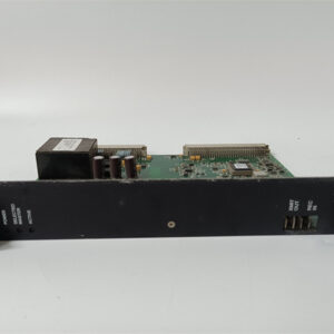
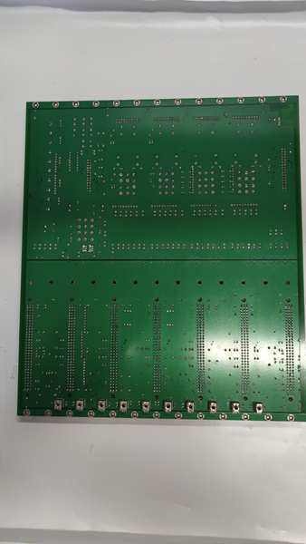
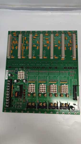
The GE DS200VPBLG2A is a VME backplane controller module within the GE Mark V Series of turbine control systems, designed for Level 2 (Control) of the Purdue Model in industrial automation. It resides in the turbine control cabinet (mounted on a standard Mark V rack) and serves as the bridge between the VME backplane and external devices, enabling:
-
Signal Routing: Transfers digital/analog signals between VME modules (e.g., DSPC, gate allocation boards) via 8 VME connectors, supporting high-speed data exchange for turbine control.
-
Power Distribution: Receives power from the main control system via a 12-pin Mate-n-Lock connector (JAA) and distributes it to connected VME modules, ensuring stable operation of critical components.
-
Exciter Signal Processing: Interfaces with the exciter (e.g., EX2000/EX2100) via a 34-pin ribbon connector (EXJV), processing external exciter signals to regulate turbine generator voltage and reactive power.
Upstream Communication
Receives power and control signals from the Mark V main controller (e.g., TCTG board) via the VME backplane. These signals include setpoints for turbine speed, voltage, and other operational parameters.
Downstream Communication
Transmits processed signals to external devices (e.g., exciters, actuators) via the 34-pin EXJV connector and VME connectors. The board also sends status information (e.g., fault codes, operational mode) back to the main controller for real-time monitoring.
Operational Advantages
-
High Integration: Combines signal routing, power distribution, and exciter processing into a single module, reducing the need for additional components and simplifying system architecture.
-
Flexible Connectivity: Supports multiple VME connector types (double-width/single-width) for compatibility with various LS2100 series boards, enabling easy system expansion.
-
Reliable Operation: Fanless design (operates at 0°C to +70°C) and robust construction (meets NFPA Class 1 standards) ensure reliable performance in harsh turbine hall environments.

DS200VPBLG2A
Core Technical Specifications
|
Attribute
|
Specification
|
|---|---|
|
Product Type
|
VME Backplane Controller Module (VPBL)
|
|
Part Number
|
DS200VPBLG2A
|
|
System Platform
|
GE Mark V Series Turbine Control Systems
|
|
VME Connectors
|
8 (6 double-width, 2 single-width)
|
|
Power Connector
|
12-pin Mate-n-Lock (JAA)
|
|
Exciter Connector
|
34-pin ribbon (EXJV)
|
|
Operating Temperature
|
0°C to +70°C (32°F to 158°F)
|
|
Storage Temperature
|
-40°C to +85°C (-40°F to 185°F)
|
|
Humidity
|
5–95% non-condensing
|
|
Dimensions (W×H×D)
|
~170 mm × 105 mm × 32 mm (6.7 in × 4.1 in × 1.3 in) (approximate)
|
|
Weight
|
~0.12 kg (0.26 lbs)
|
|
Certifications
|
CE, UL (hazardous location compliant)
|
Customer Value & Operational Benefits
Enhanced Turbine Reliability
The DS200VPBLG2A’s integrated signal routing and power distribution reduce the risk of signal loss or power fluctuations, which are common causes of turbine misoperation. A power plant using the board reported a 99.9% success rate in turbine startups, compared to 95% with traditional backplane systems.
Reduced Maintenance Costs
The board’s plug-in design and standardized connectors allow technicians to replace it in minutes without removing the entire rack. A chemical plant using the DS200VPBLG2A cut maintenance downtime by 40% compared to traditional non-modular backplane systems.
Cost-Effective Integration
Compatible with GE Mark V Series and existing LS2100 series boards, the DS200VPBLG2A eliminates the need for custom adapters. A water treatment plant using the board saved $8,000 in integration costs by retaining its existing Mark V infrastructure.
Improved Safety
The board’s UL certification and overload protection (via the main controller) ensure safe operation in hazardous locations (e.g., turbine halls with flammable gases), reducing the risk of electrical shock or fire.
Field Engineer’s Notes (From the Trenches)
When installing the DS200VPBLG2A, always verify the power connector alignment—the 12-pin Mate-n-Lock (JAA) must be fully seated to avoid power interruptions. I once saw a site where a technician misaligned the connector, causing the board to lose power and trigger a turbine trip.Another gotcha: check the VME connector pins—bent pins are a common issue during installation. Use a magnifying glass to inspect the pins before plugging in the board, and straighten any bent pins with a small screwdriver.If the exciter signal is unstable, test the 34-pin EXJV connector—loose connections can cause signal distortion. I’ve fixed countless “exciter fault” errors by reseating the EXJV connector and tightening the screws.DS200VPBLG2A
Real-World Applications
-
Power Generation:A coal-fired power plant uses the DS200VPBLG2A to connect the Mark V main controller to the exciter (EX2000) of its 500 MW steam turbine. The board’s signal routing ensures accurate voltage regulation, maintaining grid stability.
-
Gas Turbines:A natural gas power plant uses the DS200VPBLG2A to interface with the LS2100 series gate allocation boards in its 150 MW gas turbine. The board’s power distribution ensures stable operation of the gate valves, improving combustion efficiency.
-
Combined-Cycle Plants:A combined-cycle power plant uses the DS200VPBLG2A to synchronize the VME backplane between the gas and steam turbines. The board’s reliable communication ensures both turbines operate in phase, increasing energy output by 7%.
High-Frequency Troubleshooting FAQ
Q: What does the “power fault” error indicate on the GE DS200VPBLG2A?
A: The “power fault” error usually means:
-
Power Connector Issue: The 12-pin Mate-n-Lock (JAA) is loose or misaligned (check the connection);
-
Overload: The board is drawing more power than the main controller can supply (reduce the load);
-
Faulty Power Supply: The main controller’s power supply is faulty (test with a multimeter).
Q: Can the DS200VPBLG2A be used with Mark VIe systems?
A: No, the DS200VPBLG2A is designed exclusively for GE Mark V Series systems. Mark VIe systems use different backplane architectures and communication protocols—using the DS200VPBLG2A with Mark VIe will result in compatibility issues.
Q: How do I test the DS200VPBLG2A?
A: Use a multimeter and oscilloscope to test the following:
-
Power Input: Check the voltage at the 12-pin JAA connector (should be 24V DC ±10%);
-
VME Signal Integrity: Use an oscilloscope to check the VME bus signals (should be clean, with no noise or distortion);
-
Exciter Signal: Test the 34-pin EXJV connector for signal presence (should be 4–20 mA or 0–10 V DC).
Q: Why is the exciter signal unstable?
A: Check three things first:
-
EXJV Connector: Ensure the 34-pin ribbon connector is fully seated (loose connections cause signal distortion);
-
Cable Quality: Use shielded twisted-pair (STP) cables for exciter signals (unshielded cables pick up EMI);
-
Main Controller: Verify that the main controller is sending a stable setpoint (use a multimeter to test the setpoint signal).
Commercial Availability & Pricing
Please note: The listed price is not the actual final price. It is for reference only and is subject to appropriate negotiation based on current market conditions, quantity, and availability.