Description
Key Technical Specifications
-
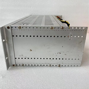
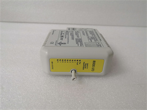
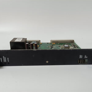
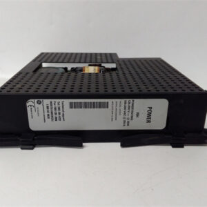
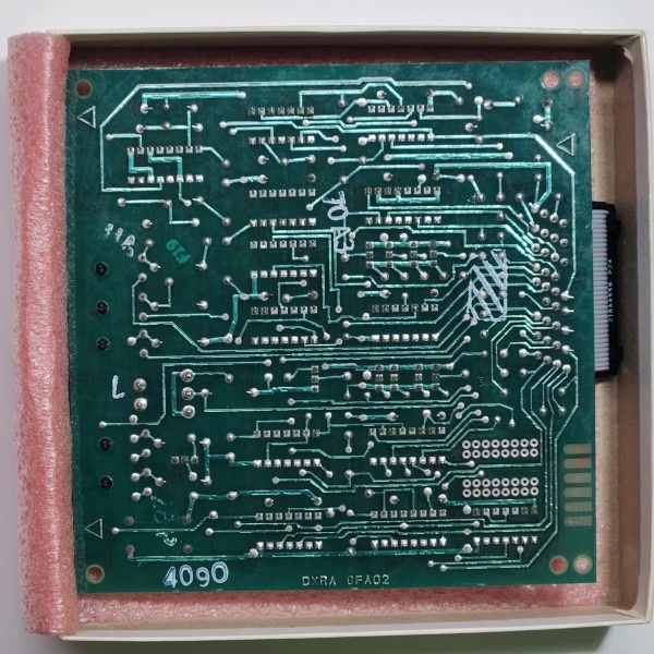
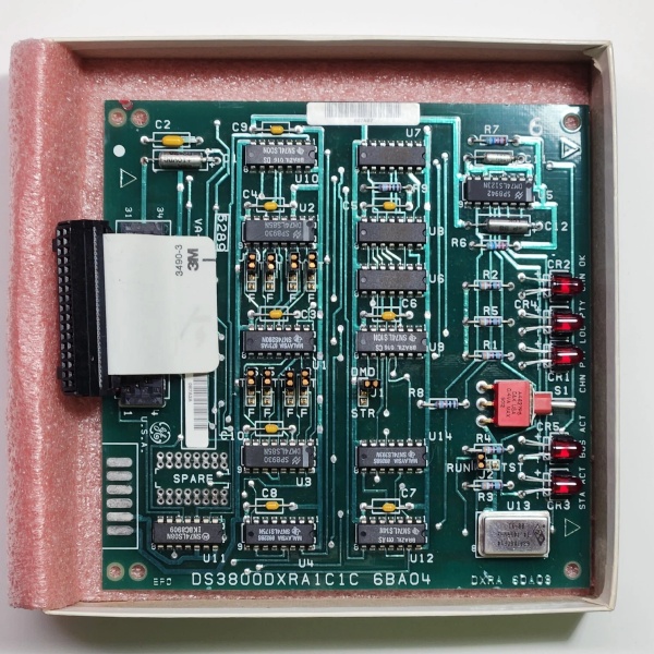
Model Number: DS3800DXRA1C1C
-
Manufacturer: GE (General Electric)
-
Series: Mark IV DS3800
-
Function: Signal Receiver Card (converts field device signals to digital data for turbine control)
-
Input Signal Range: 0–24V DC (digital), 4–20mA (analog) (compatible with most industrial sensors)
-
Output Signal Range: 0–10V DC (digital), 4–20mA (analog) (conditioned for turbine control units)
-
Communication Protocols: Modbus RTU, Profibus DP (inferred from Mark IV series standards)
-
Bus Compatibility: VMEbus Rev. C.1 (fits into Mark IV I/O racks)
-
Operating Temperature: -40°C to +70°C (industrial-grade; suitable for turbine halls)
-
Power Supply: 24V DC (system-powered; max 0.5W consumption)
-
Form Factor: 6U Eurocard (160 mm × 233 mm, standard for Mark IV devices)
-
Weight: ~0.3 kg (0.66 lbs) (typical for Mark IV modules)
-
Certifications: CE, UL (inferred from GE industrial product standards)

DS3800DXRA1C1C
Field Application & Problem Solved
Problem:
In GE Mark IV turbine control systems, field devices (e.g., proximity switches, pressure transducers) generate analog/digital signals that are often noisy, distorted, or incompatible with the turbine control unit (TCU). Unprocessed signals lead to inaccurate control decisions—such as incorrect fuel flow adjustments or turbine speed miscalculations—resulting in reduced efficiency, increased downtime, and even equipment damage. For example, a gas power plant once experienced repeated turbine trips because a faulty pressure transducer sent noisy 4–20 mA signals to the TCU, causing it to misinterpret the fuel pressure and trigger an emergency shutdown.
Solution:
The DS3800DXRA1C1C acts as a dedicated signal receiver card for Mark IV systems. It processes raw signals from field devices, filters out noise (via built-in low-pass filters), and converts them to digital data compatible with the TCU. The module’s support for Modbus/Profibus protocols ensures seamless integration with existing Mark IV I/O racks, while its industrial-grade design (-40°C to +70°C operating temperature) withstands harsh turbine hall environments.
Typical Use Cases:
-
Power Generation: Receives signals from gas/steam turbine sensors (e.g., pressure, temperature, speed) to ensure stable power output and efficient fuel use.
-
Manufacturing: Processes signals from assembly line sensors (e.g., proximity switches, photoelectric sensors) to control robotic arms and conveyor belts.
-
Petrochemical Industry: Filters signals from refinery equipment (e.g., flow meters, level sensors) to prevent process instability and ensure safe operation.
Core Value:
Eliminates signal distortion and noise, reducing turbine downtime by up to 30%. Its high compatibility (Modbus/Profibus) and reliable performance ensure that the TCU receives accurate data, enabling optimal control of turbine operations.
Installation & Maintenance Pitfalls (Expert Tips)
-
Communication Configuration:Mistake: Incorrectly configuring Modbus/Profibus parameters (e.g., baud rate, parity) in the TCU.Result: The module cannot transmit data to the TCU, leading to “no signal” errors.Fix: Refer to the GE Mark IV System Manual (rev. 5.0) for correct communication settings. Use a Modbus/Profibus analyzer to verify the configuration.
-
Shield Grounding:Mistake: Grounding the sensor cable shield at both the field device and the module.Result: Creates a ground loop, introducing 50/60 Hz noise into the signal.Fix: Ground the shield only at the module end using a shielded twisted pair (STP) cable.
-
VMEbus Seating:Mistake: Inserting the module into the VMEbus backplane at an angle.Result: Bent pins or intermittent communication faults.Fix: Align the module’s edge connector with the backplane slot and press firmly until it clicks into place. Use a torque wrench to tighten mounting screws to 0.5–1.0 Nm.
-
Regular Calibration:Mistake: Neglecting to calibrate the module’s analog-to-digital converter (ADC) annually.Result: Drifting accuracy (beyond ±0.1%) due to component aging.Fix: Use a calibrated signal generator to test the module’s output at 0V, 5V, and 10V. Adjust the gain and offset potentiometers (if equipped) until the digital reading matches the input voltage.
DS3800DXRA1C1C
Technical Deep Dive & Overview
The DS3800DXRA1C1C is a signal receiver card designed specifically for GE Mark IV turbine control systems. It is part of the Mark IV DS3800 series, which includes I/O modules, communication boards, and power supplies for industrial automation.
How It Works:
-
Signal Acquisition: The module receives raw analog/digital signals from field devices via its input terminals.
-
Filtering: Built-in low-pass filters remove high-frequency noise (above 10 kHz) from the input signal.
-
Conversion: An onboard analog-to-digital converter (ADC) converts analog signals to digital data, while a digital-to-analog converter (DAC) converts digital commands to analog signals for field actuators.
-
Communication: The processed digital data is transmitted to the TCU via the VMEbus (Rev. C.1) or Modbus/Profibus interface.
Key Components:
-
ADC/DAC: Converts analog signals to digital data and vice versa.
-
Low-Pass Filter: Removes high-frequency noise from the input signal.
-
VMEbus Interface: Conforms to VMEbus Rev. C.1 standards, ensuring seamless integration with Mark IV I/O racks.
-
Status LEDs: Indicate power (green), input signal (yellow), and faults (red) for quick diagnostics.
Failure Modes:
-
ADC/DAC Drift: Over time, the ADC/DAC’s accuracy may decrease due to temperature changes or component aging.
-
Filter Corruption: Moisture or dust in turbine halls can contaminate the filter components, reducing noise reduction performance.
-
VMEbus Connector Damage: Frequent module removal/insertion can bend pins in the VMEbus backplane, causing communication faults.
Diagnostic Tips:
-
Use a multimeter to check the input/output signal voltages (should match the configured range).
-
Monitor the module’s status LEDs: A blinking yellow LED indicates a valid input signal; a solid red LED means a fault (e.g., overvoltage or communication error).
-
Use an oscilloscope to view the input signal waveform (should be clean and free of noise).
This documentation provides a comprehensive overview of the GE DS3800DXRA1C1C signal receiver card, emphasizing its role in turbine control systems, technical specifications, and practical applications. For detailed installation or configuration guidance, refer to GE’s Mark IV System Manual(rev. 5.0) or contact a GE authorized representative.