Description
Key Technical Specifications
-
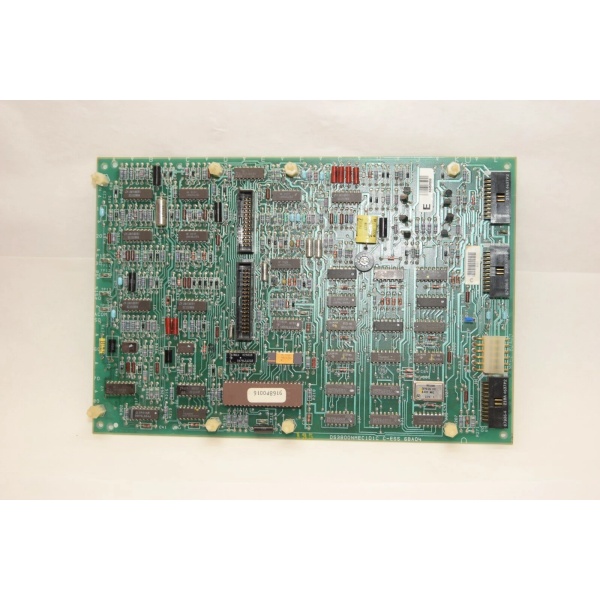
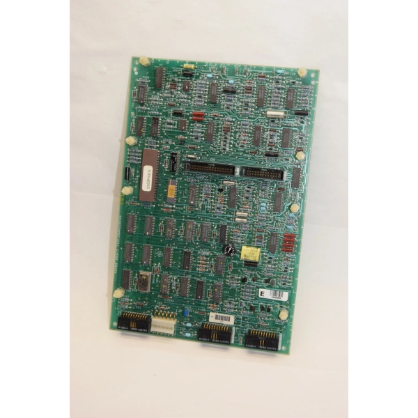
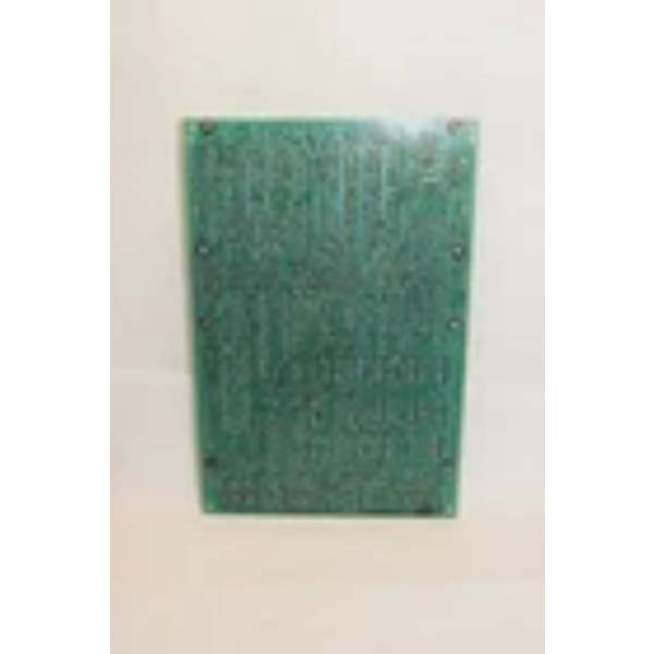
Model Number: DS3800HISA1B1B
-
Manufacturer: GE (General Electric)
-
Protocol Support: GE Mark IV proprietary, Modbus RTU (limited)
-
Ports: 8 digital inputs (configurable for sinking/sourcing)
-
Data Rate: 1 kHz max per channel (software adjustable)
-
Operating Temperature: -40°C to +70°C
-
Isolation: 3000Vrms channel-to-ground, 1500Vrms channel-to-channel
-
Input Voltage: 24V DC ±30% (sink current: 20mA max per channel)
-
Certifications: UL AWM Style 2083, CE EN 61000-6-2/4
-
Weight: 0.5 kg (1.1 lbs)
-
Mounting: DIN rail or Mark IV chassis (6U Eurocard)

DS3800NMEC1D1C
Field Application & Problem Solved
Problem:
In turbine control systems, field devices (e.g., proximity switches, limit switches) generate noisy 24V signals. Without isolation, voltage spikes from motor starters or transient faults currents fry control logic boards. A single unisolated input failure can cascade into a turbine trip, costing $100k+/hour in lost generation.
Solution:
The DS3800HISA1B1B acts as a “signal firewall.” Its optocouplers electrically isolate each input channel, blocking ground loops and spikes. For example, in a steam turbine’s vibration monitoring system, proximity switches detect blade wear. Without isolation, a ground fault from a faulty sensor could corrupt the entire control network. This module ensures only clean, isolated signals reach the CPU.
Typical Use Cases:
-
Power Plants: Interfacing with old analog sensors in coal-fired plants upgraded to Mark IV systems.
-
Refineries: Reading level switches in hazardous areas (Zone 2) without risking explosion-proof enclosure breaches.
-
Paper Mills: Handling high-shock/vibration inputs from roller position sensors.
Core Value:
Prevents nuisance trips caused by signal corruption. A single isolated input module can replace 3+ non-isolated modules in legacy systems, cutting wiring complexity by 40%.
Installation & Maintenance Pitfalls
1. Ignoring Shield Grounding
-
Issue: The module’s shield must connect to the backplane ground at one point only. Multiple ground connections create ground loops, inducing noise.
-
Fix: Use a star-grounding scheme. Terminate the shield at the Mark IV chassis ground lug, notthe DIN rail.
2. Mismatched Termination Resistors
-
Issue: RS-485 networks require 120Ω termination at both ends. Missing resistors cause reflections, corrupting high-speed inputs.
-
Fix: Install 120Ω resistors at the module’s terminal block (terminals 1 and 2 for RS-485).
3. Overloading Input Circuits
-
Issue: Exceeding 20mA per channel blows input fuses (0.1A slow-blow). Common with miswired 4-20mA sensors.
-
Fix: Use pull-up resistors (4.7kΩ) on sinking inputs to limit current.
4. Software Configuration Errors
-
Issue: Polling rates >1 kHz cause input debounce failures. A proximity switch bouncing at 50Hz gets misread as 50% duty cycle.
-
Fix: Set scan intervals to 10ms (100Hz) or enable hardware debouncing (config bit 0x04).
DS3800NMEC1D1C
Technical Deep Dive
The DS3800HISA1B1B uses dual-channel optoisolation per input. Each channel has a gallium arsenide LED paired with a phototransistor, electrically separating the field side (24V) from the logic side (5V). When a 24V signal activates, the LED emits light, triggering the phototransistor to pull the input low (0V). Isolation barriers block transient voltages >3000Vrms.
Signal Flow:
-
Field device → Terminal block (24V input)
-
Optoisolator → Converts 24V to 5V logic signal
-
Schmitt trigger → Debounces noisy edges (adjustable 0.1-10ms)
-
Backplane bus → Transfers data to Mark IV CPU
Failure Modes:
-
Optoisolator Degradation: UV exposure in turbine halls degrades GaAs LEDs over 10+ years. Symptom: Intermittent “input stuck high/low.”
-
Backplane Arc Flash: Improper VMEbus grounding during maintenance can fry the module’s edge connector.
Pro Tip: Use a thermal camera to check for hot spots (>85°C) on the optoisolator IC. Overheating indicates impending failure.