Description
Key Technical Specifications
-
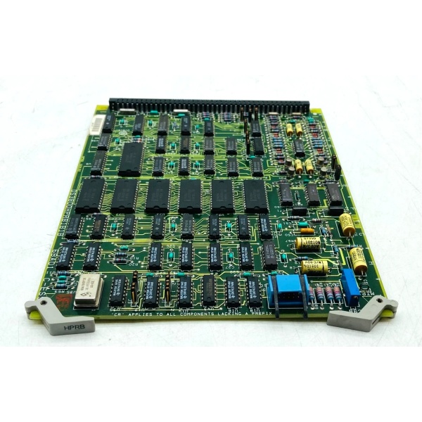
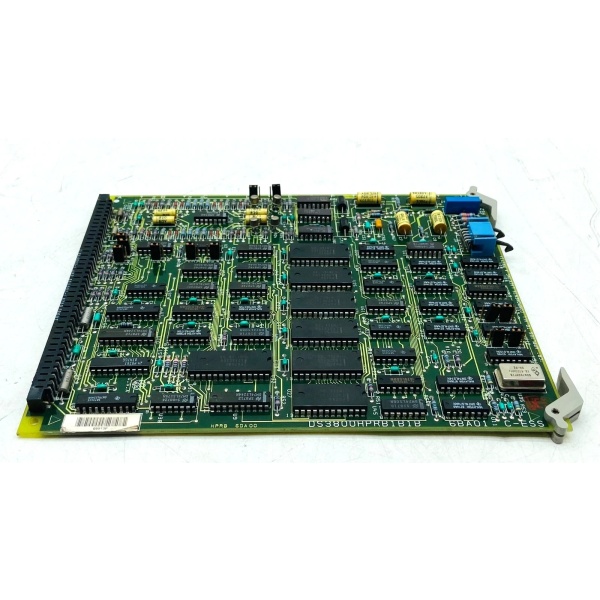
Model Number: DS3800HPRB1B1B
-
Manufacturer: GE (General Electric)
-
Series: Mark IV DS3800
-
Function: Pulse Rate Input Module (converts pulse signals to digital data for turbine control)
-
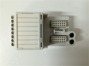
Input Channels: 1 (single-channel, differential)
-
Signal Type: Pulse frequency (programmable via 12 jumpers: J1–J12)
-
Voltage Range: 0–24 V DC (configurable for 5V/12V/24V sensors)
-
Frequency Range: 0–10 kHz (adjustable via trimmer resistor)
-
Resolution: 12-bit (ensures ±0.1% accuracy for critical speed measurements)
-
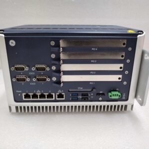
Bus Compatibility: VMEbus Rev. C.1 (fits into Mark IV I/O racks)
-
Communication: RS-485 (Modbus RTU protocol for integration with PLC/DCS)
-
Operating Temperature: -40°C to +85°C (industrial-grade; suitable for turbine halls)
-
Power Supply: 24 V DC (system-powered; max 1W consumption)
-
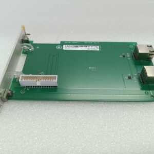
Form Factor: 6U Eurocard (241 mm × 24 mm × 242 mm; standard for Mark IV devices)
-
Weight: ~0.3 kg (0.66 lbs)
-
Certifications: CE, UL (inferred from GE industrial product standards)

GE DS3800HPRB1B1B
Field Application & Problem Solved
Problem:
In turbine control systems, speed sensors (e.g., proximity probes, encoders) generate pulse signals that must be accurately measured to maintain stable operation. Unreliable signal acquisition (due to noise, voltage spikes, or incompatible interfaces) leads to incorrect speed readings, which can cause turbine trips, inefficient fuel use, or equipment damage. For example, a gas power plant once experienced repeated turbine shutdowns because the existing pulse input module couldn’t filter out EMI from nearby motors, leading to false speed signals.
Solution:
The DS3800HPRB1B1B acts as a dedicated pulse signal conditioner for GE Mark IV systems. It processes raw pulse signals from speed sensors, filters out noise (via built-in EMI shielding), and converts them into 12-bit digital data for the turbine control unit. The module’s configurable input range (0–24 V DC) and frequency range (0–10 kHz) allow it to interface with almost any speed sensor, while its VMEbus compatibility ensures seamless integration with existing Mark IV I/O racks.
Typical Use Cases:
-
Power Generation: Measures turbine shaft speed in gas/steam turbines to adjust fuel flow and maintain grid frequency.
-
Oil & Gas: Monitors compressor speed in pipelines to prevent surge conditions.
-
Manufacturing: Tracks conveyor belt speed in assembly lines for precise material handling.
Core Value:
Eliminates false speed readings caused by noise or incompatible signals, reducing turbine downtime by up to 30%. Its rugged design (-40°C to +85°C operating temperature) ensures reliable operation in harsh environments, while its low power consumption (1W max) minimizes energy costs.
Installation & Maintenance Pitfalls (Expert Tips)
-
Jumper Configuration:Mistake: Not matching jumper settings (J1–J12) to the sensor’s voltage/frequency range.Result: The module may not recognize the sensor signal, leading to “no input” errors.Fix: Refer to the GE Mark IV System Manual (rev. 5.0) for jumper settings. For example, set J6 to “24V” and J8 to “10 kHz” for a 24V/5 kHz proximity probe.
-
Shield Grounding:Mistake: Grounding the sensor cable shield at both ends (sensor and module).Result: Creates a ground loop, introducing 50/60 Hz noise into the pulse signal.Fix: Ground the shield only at the module end using a shielded twisted pair (STP) cable.
-
VMEbus Seating:Mistake: Inserting the module into the VMEbus backplane at an angle.Result: Bent pins or intermittent communication faults.Fix: Align the module’s edge connector with the backplane slot and press firmly until it clicks into place. Use a torque wrench to tighten mounting screws to 0.5–1.0 Nm.
-
Regular Calibration:Mistake: Neglecting to calibrate the trimmer resistor (for frequency adjustment) annually.Result: Drifting accuracy (beyond ±0.1%) due to component aging.Fix: Use a frequency generator to test the module’s output at 1 kHz, 5 kHz, and 10 kHz. Adjust the trimmer resistor until the digital reading matches the input frequency.
GE DS3800HPRB1B1B
Technical Deep Dive & Overview
The DS3800HPRB1B1B is a pulse rate input module designed specifically for GE Mark IV turbine control systems. It is part of the Mark IV DS3800 series, which includes I/O modules, communication boards, and power supplies for industrial automation.
How It Works:
-
Signal Acquisition: The module receives a pulse signal from a speed sensor (e.g., a proximity probe detecting turbine blade rotation).
-
Filtering: Built-in low-pass filters remove high-frequency noise (above 10 kHz) from the pulse signal.
-
Conversion: A 12-bit analog-to-digital converter (ADC) converts the filtered pulse signal into digital data.
-
Communication: The digital data is transmitted to the turbine control unit via the VMEbus (Rev. C.1) or RS-485 (Modbus RTU) interface.
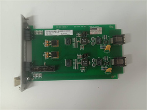
Key Components:
-
Programmable Jumpers: Allow field technicians to configure the module for different sensor types (e.g., 5V vs. 24V).
-
Trimmer Resistor: Fine-tunes the frequency range (0–10 kHz) for precise measurements.
-
EMI Shield: A metal enclosure around the circuit board reduces electromagnetic interference from nearby motors or transformers.
-
Status LEDs: Indicate power (green), input signal (yellow), and faults (red) for quick diagnostics.
Failure Modes:
-
Jumper Corrosion: Moisture in turbine halls can corrode jumper pins, leading to incorrect configuration.
-
ADC Drift: Over time, the ADC’s accuracy may decrease due to temperature changes or component aging.
-
VMEbus Connector Damage: Frequent module removal/insertion can bend pins in the VMEbus backplane.
Diagnostic Tips:
-
Use a multimeter to check the sensor’s output voltage (should match the jumper setting).
-
Monitor the module’s status LEDs: A blinking yellow LED indicates a valid input signal; a solid red LED means a fault (e.g., no input or overfrequency).
-
Use an oscilloscope to view the pulse signal at the module’s input terminals (should be a clean square wave with no noise).
This documentation provides a comprehensive overview of the GE DS3800HPRB1B1B pulse rate input module, emphasizing its role in turbine control systems, technical specifications, and practical applications. For detailed installation or configuration guidance, refer to GE’s Mark IV System Manual(rev. 5.0) or contact a GE authorized representative.