Description
Key Technical Specifications
-
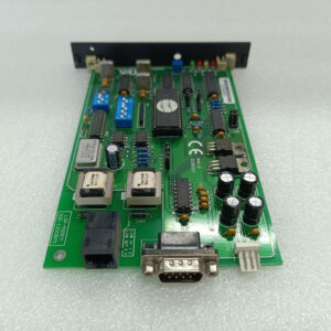
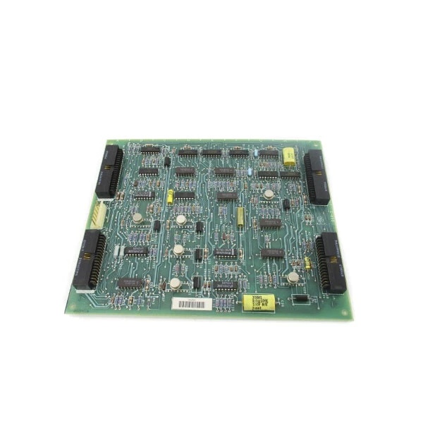
Model Number: DS3800NCID1C1C
-
Manufacturer: GE (General Electric)
-
Isolation Voltage: 1500Vrms (channel-to-ground, typical for Mark IV isolators)
-
Input Signal Types: 4–20 mA analog current (configurable for 0–20 mA)
-
Output Signal Types: 4–20 mA conditioned current (isolated)
-
Accuracy: ±0.1% of full scale (typical for Mark IV signal conditioning)
-
Bandwidth: 10 Hz–10 kHz (suitable for process control applications)
-
Bus Compatibility: VMEbus Rev. C.1 (fits into Mark IV I/O racks)
-
Form Factor: 6U Eurocard (160 mm × 233 mm, standard for Mark IV devices)
-
Operating Temperature: -40°C to +70°C (industrial-grade)
-
Weight: ~0.5 kg (1.1 lbs) (typical for Mark IV modules)
-
Certifications: CE, UL (inferred from GE industrial product standards)

GE DS3800NGRC1F1F
Field Application & Problem Solved
Problem:
In turbine control systems, field devices like pressure transducers and flow meters generate 4–20 mA current signals that are susceptible to noise, voltage spikes, and ground loops. These issues corrupt the signals, leading to inaccurate process control (e.g., incorrect fuel flow adjustments) and potential turbine damage. A single corrupted signal can cause a turbine trip, resulting in significant downtime and revenue loss.
Solution:
The DS3800NCID1C1C acts as a signal conditioner and isolator. It uses galvanic isolation (via optocouplers or isolation amplifiers) to separate the field device signals from the control unit, blocking noise and voltage spikes. The module also conditions the signals (e.g., filtering, scaling) to ensure they are in a format suitable for the turbine control unit. For example, in a gas power plant, the board isolates the 4–20 mA signal from a fuel flow meter, preventing ground loop noise from affecting the control algorithm.
Typical Use Cases:
-
Power Plants: Isolating current signals from pressure transducers in gas/steam turbines to ensure accurate fuel flow control.
-
Refineries: Conditioning current signals from flow meters in distillation columns to prevent process instability.
-
Paper Mills: Isolating current signals from tension sensors in paper machines to maintain consistent product quality.
Core Value:
Prevents signal corruption caused by noise and ground loops, ensuring accurate process control. The module’s rugged design (-40°C to +70°C operating temperature) allows it to survive in harsh turbine environments, reducing the need for frequent replacements.
Installation & Maintenance Pitfalls (Expert Tips)
-
Incorrect Wiring:Mistake: Reversing the input and output wires or using the wrong terminal block.Result: The module will not isolate the signal correctly, leading to noise and inaccurate readings.Fix: Follow the wiring diagram in the GE Mark IV System Manual (rev. 5.0) carefully. Use the correct terminal block (e.g., 218A4637-P4) for input/output connections.
-
Poor Grounding:Mistake: Grounding the module to a non-isolated ground or failing to ground the shield.Result: Introduces ground loops, causing 50/60 Hz noise in the signal.Fix: Ground the module to the Mark IV chassis ground (single-point grounding). Use shielded twisted pair (STP) cable for field device connections and ground the shield at the module end.
-
Overloading the Input:Mistake: Connecting a field device with a higher current output (e.g., 0–25 mA) to the module.Result: Damages the input stage of the module, leading to permanent failure.Fix: Ensure the field device’s output current is within the module’s specified range (4–20 mA). Use a current divider if necessary to reduce the signal amplitude.
-
Neglecting Regular Maintenance:Mistake: Failing to clean the module’s connectors or check for loose wires.Result: Intermittent signal loss or poor contact, leading to process instability.Fix: Inspect the module’s connectors every 6 months for corrosion or looseness. Clean the connectors with a contact cleaner (e.g., DeoxIT) if necessary.
GE DS3800NGRC1F1F
Technical Deep Dive & Overview
The DS3800NCID1C1C is a current isolator board designed for GE Mark IV turbine control systems. It uses galvanic isolation to separate the field device signals from the control unit, preventing noise and voltage spikes from affecting the control algorithm. The module’s key functions include:
-
Signal Isolation: Uses optocouplers or isolation amplifiers to block common-mode noise and ground loops.
-
Signal Conditioning: Filters the input signal to remove high-frequency noise and scales it to the desired output range (e.g., 4–20 mA to 0–10 V DC).
-
VMEbus Communication: Conforms to VMEbus Rev. C.1 standards, allowing it to communicate with the Mark IV CPU and other I/O modules.
How It Works:
-
Input Stage: The field device’s 4–20 mA current signal is converted to a voltage signal using a precision resistor (e.g., 250 Ω).
-
Isolation Stage: The voltage signal is passed through an optocoupler or isolation amplifier, which blocks any noise or voltage spikes.
-
Output Stage: The isolated voltage signal is converted back to a 4–20 mA current signal using a current output amplifier.
-
Communication: The module communicates with the Mark IV CPU via the VMEbus, sending the conditioned signal for further processing.
Failure Modes:
-
Optocoupler Degradation: Prolonged exposure to high temperatures or humidity can degrade the optocouplers, leading to reduced isolation performance.
-
Connector Corrosion: Corrosion on the terminal blocks can cause poor contact, leading to intermittent signal loss.
-
Power Supply Issues: A faulty power supply can cause the module to malfunction, leading to incorrect signal conditioning.
Diagnostic Tips:
-
Use a multimeter to check the input and output current signals (should be 4–20 mA).
-
Monitor the module’s status LED (if equipped): Blinking = normal operation; Solid = fault.
-
Use an oscilloscope to check for noise on the input signal (should be <10 mV peak-to-peak).